
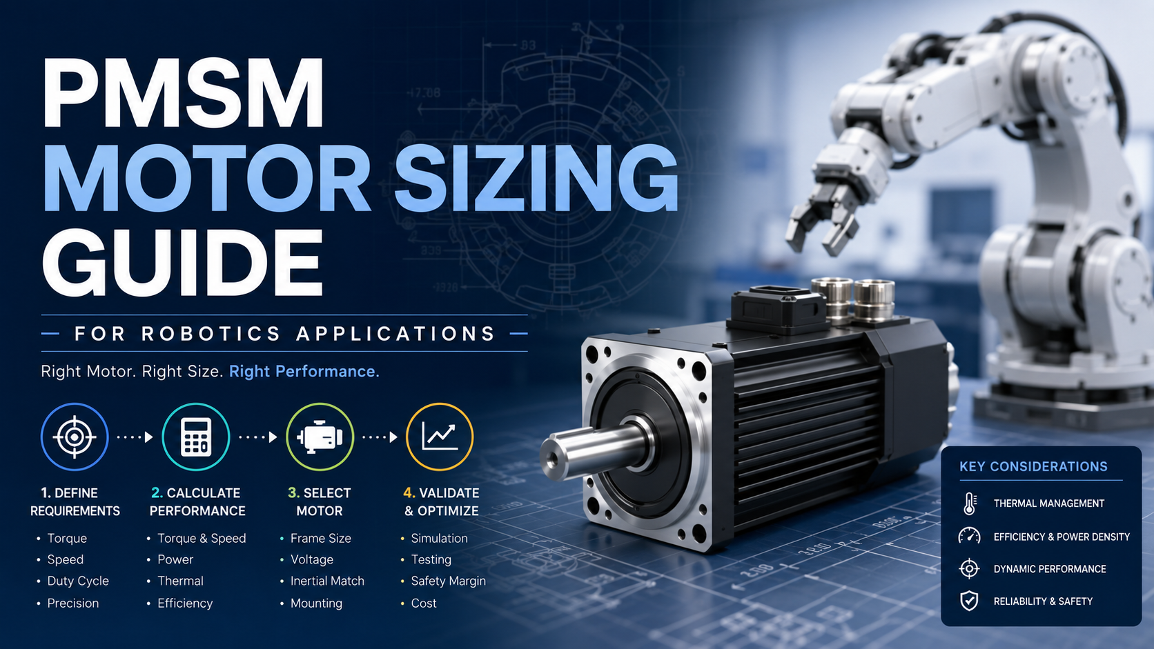
Selecting the correct PMSM motor is one of the most important decisions in robotic system design. An undersized motor causes overheating, positioning errors, and reduced service life, while an oversized motor increases cost, weight, and energy consumption.
This guide explains how engineers calculate motor size for robotic joints, AGVs, collaborative robots, industrial manipulators, and automated equipment using practical engineering methods.
Quick Answer for PMSM Motor Sizing Guide
To size a PMSM motor for robotics:
Define the payload and moving mass.
Calculate required continuous torque.
Calculate peak acceleration torque.
Determine operating speed.
Estimate duty cycle.
Match motor inertia with load inertia.
Verify thermal limits.
Add an engineering safety margin of approximately 20–30%.
Proper sizing improves positioning accuracy, efficiency, reliability, and motor lifetime.
Primary references: IEEE Industry Applications Society (2023), NIST Robotics publications, IEC 60034 Motor Standards, Siemens Motion Control Engineering Handbook.
Why PMSM Motors Are Preferred in Robotics?
Permanent Magnet Synchronous Motors (PMSMs) have become the preferred choice for modern robotic systems because they combine:
- High torque density
- Excellent dynamic response
- High positioning accuracy
- High efficiency
- Compact dimensions
- Low maintenance
Unlike brushed motors, PMSMs eliminate brush wear. Compared with induction motors, they achieve higher efficiency and faster response, making them suitable for precision servo applications.
According to the U.S. Department of Energy (DOE, 2024), permanent magnet motor technologies generally provide higher efficiency than comparable induction motors, especially under partial-load conditions.
Source: U.S. Department of Energy, Electric Motor Systems, 2024.
Understanding PMSM Motor Sizing
Motor sizing means selecting a motor capable of delivering:
- Required torque
- Required speed
- Required acceleration
- Required precision
- Required thermal performance
Motor selection should never rely solely on rated power.
For robotic applications, torque and inertia matching are typically more important than horsepower.
Step 1. Define Robot Motion Requirements
Begin by identifying the application.
Typical robotic applications include:
- Industrial robot arms
- Collaborative robots
- Autonomous mobile robots (AMRs)
- Automated Guided Vehicles (AGVs)
- SCARA robots
- Delta robots
- Medical robots
- Inspection robots
Collect the following data:
| Parameter | Typical Unit |
| Payload | kg |
| Link length | mm |
| Moving mass | kg |
| Maximum speed | rpm or rad/s |
| Acceleration time | ms |
| Duty cycle | % |
| Required positioning accuracy | mm or arc-min |
Without these parameters, accurate motor sizing is impossible.
Step 2. Calculate Required Torque
Torque is the most important sizing parameter.
The total torque consists of:
- Load torque
- Acceleration torque
- Friction torque
- Gravity torque (vertical axes)
The general equation is:
Total Torque = Load Torque + Acceleration Torque + Friction Torque
For rotary systems:
T = J × α
Where:
T = torque (Nm)
J = rotational inertia (kg·m²)
α = angular acceleration (rad/s²)
For linear robots using ballscrews:
Torque = (Force × Lead) / (2π × Efficiency)
Engineers should always calculate both:
Continuous torque
Peak torque
Peak torque usually occurs during acceleration.
According to IEEE Industry Applications Society (2023), acceleration torque often dominates servo motor sizing in high-speed robotic systems.
Source: IEEE IAS Motor Drive Design Guidelines, 2023.
Step 3. Determine Required Speed
Motor speed depends on application requirements.
Examples:
| Robot Type | Typical Motor Speed |
| Cobot joint | 500–3,000 rpm |
| Industrial robot | 1,000–5,000 rpm |
| AGV drive | 500–4,000 rpm |
| Delta robot | 3,000–6,000 rpm |
If a gearbox is used:
Motor Speed = Output Speed × Gear Ratio
Never select the motor based only on maximum speed.
Continuous operating speed is usually more important.
Step 4. Match Load Inertia
One of the biggest mistakes in robotic motor sizing is ignoring inertia matching.
The inertia ratio is:
Load Inertia / Motor Inertia
Typical recommendations:
- Direct drive: 1:1 to 3:1
- Servo systems: below 5:1
- With advanced servo tuning: up to 10:1
Higher inertia ratios reduce:
- Servo stability
- Dynamic response
- Position accuracy
Excessive inertia may also increase vibration and overshoot.
According to servo motion control design recommendations published by Siemens, inertia matching significantly improves closed-loop stability and tuning performance.
Source: Siemens Motion Control Engineering Manual, latest edition.
Step 5. Evaluate Duty Cycle
Robots rarely operate continuously at maximum torque.
Instead, engineers analyze the motion profile.
Typical motion includes:
- Accelerate
- Constant speed
- Decelerate
- Hold position
Calculate RMS torque:
RMS Torque = √[(T₁²t₁ + T₂²t₂ + …)/Total Time]
The motor’s continuous torque rating must exceed RMS torque.
Ignoring RMS calculations often results in motor overheating.
Step 6. Verify Thermal Performance
Thermal limits usually determine motor lifetime.
Important temperatures include:
- Ambient temperature
- Winding temperature
- Housing temperature
Typical insulation classes:
| Class | Maximum Temperature |
| B | 130°C |
| F | 155°C |
| H | 180°C |
Many robotic servo motors use Class F insulation with Class B temperature rise for longer service life.
According to IEC 60034, exceeding allowable winding temperatures accelerates insulation aging and reduces motor life.
Source: IEC 60034 Rotating Electrical Machines Standard.
Step 7. Add an Engineering Safety Margin
A safety margin compensates for:
- Unexpected payloads
- Mechanical wear
- Future upgrades
- Environmental variation
Typical recommendations:
- Torque reserve: 20–30%
- Speed reserve: 10–20%
- Thermal reserve: 15–20%
Oversizing beyond 50% generally reduces efficiency and increases system cost.
Typical PMSM Motor Specifications for Robotics
Typical industrial PMSM servo motors include:
- Power: 50 W–5 kW
- Rated torque: 0.16–32 Nm
- Peak torque: up to 300% rated
- Speed: 1,000–6,000 rpm
- Encoder resolution: 17–24 bit
- Efficiency: 90–97%
- Protection: IP54–IP67
- Supply voltage: 24 VDC, 48 VDC, 220 VAC, 380 VAC
Actual specifications depend on application requirements and gearbox selection.
Common PMSM Motor Selection Mistakes
Selecting by Power Only
Power alone does not determine whether the motor can meet acceleration requirements.
Always verify torque-speed curves.
Ignoring Peak Torque
Many robotic movements require short bursts of torque during acceleration.
Peak torque may be two to three times the continuous rating.
Ignoring Gearbox Efficiency
Reducers introduce efficiency losses.
Typical gearbox efficiencies:
Planetary: 94–98%
Harmonic: 70–90%
Worm: 50–90%
Motor torque calculations should include these losses.
Forgetting Load Inertia
Poor inertia matching causes:
- Oscillation
- Slow response
- Servo tuning difficulties
- Increased settling time
Underestimating Thermal Conditions
Ambient temperatures above 40°C significantly reduce continuous output capability unless additional cooling is provided.
PMSM Motor vs Other Motor Types for Robotics
| Feature | PMSM Motor | Induction Motor | Brushed DC Motor |
| Efficiency | Very High | High | Moderate |
| Position Accuracy | Excellent | Moderate | Moderate |
| Dynamic Response | Excellent | Good | Good |
| Maintenance | Low | Low | High |
| Torque Density | High | Medium | Medium |
| Servo Control | Excellent | Good | Limited |
For precision robotic systems, PMSM motors generally provide the best combination of efficiency, controllability, and compact size.
Troubleshooting Motor Sizing Problems
| Problem | Possible Cause | Recommended Solution |
| Motor overheats | Continuous torque exceeded | Recalculate RMS torque and improve cooling |
| Robot accelerates slowly | Motor undersized | Increase peak torque capacity or reduce inertia |
| Servo oscillation | High inertia ratio | Improve inertia matching or retune the servo |
| Excessive vibration | Improper mechanical coupling | Check alignment, stiffness, and balancing |
| Encoder errors | Electrical noise or loose wiring | Improve shielding and verify cable connections |
| Motor trips during acceleration | Peak current limit reached | Increase motor capacity or lengthen acceleration time |
Best Practices for Robotics Engineers
When selecting a PMSM motor, engineers should:
Begin with the motion profile rather than motor catalog values.
Calculate continuous, peak, and RMS torque separately.
Verify inertia matching before selecting a gearbox.
Consider gearbox efficiency in torque calculations.
Confirm thermal performance under the expected ambient conditions.
Reserve additional capacity for future payload changes and system expansion.
Validate the design through simulation and prototype testing before mass production.
A systematic sizing process reduces commissioning time and improves long-term reliability.
Why Choose UNITED MOTION INC.?
At UNITED MOTION INC., we provide custom PMSM motor and motion control solutions for robotics, automation, AGVs, medical equipment, and intelligent manufacturing systems.
Our engineering team assists customers with:
- Motor sizing calculations
- Torque and speed matching
- Gearbox selection
- Servo drive integration
- Encoder configuration
- Custom shaft and mounting design
- OEM and ODM development
By combining engineering analysis with application-specific customization, we help customers shorten development cycles and improve overall system performance.
Frequently Asked Questions
How do I calculate the required PMSM motor torque for a robot?
Calculate load torque, acceleration torque, friction torque, and gravity torque (if applicable). The selected motor’s continuous torque should exceed the RMS torque, while its peak torque should cover maximum acceleration demands with an appropriate safety margin.
What is a good inertia ratio for PMSM servo motors?
For most robotic servo systems, an inertia ratio below 5:1 provides excellent dynamic performance. Advanced servo controllers can often handle ratios up to 10:1 with careful tuning.
Should I oversize a PMSM motor?
A moderate safety margin of approximately 20–30% is recommended. Excessive oversizing increases cost, weight, and inertia while reducing operating efficiency.
Why is RMS torque important?
RMS torque represents the motor’s thermal loading over an entire motion cycle. Selecting a motor based only on peak torque can result in overheating during continuous operation.
Can one PMSM motor be used for every robot joint?
No. Each joint experiences different loads, speeds, and duty cycles. Individual motor sizing should be performed for every axis to achieve optimal performance.
Related blog: WHY PMSM MOTOR IS USED IN ELECTRIC VEHICLES?