Rotor balancing in a BLDC Motor is the process of minimizing mass imbalance in the rotating assembly to reduce vibration, noise, bearing wear, and efficiency loss. Proper rotor balancing improves motor lifespan, increases operational stability, and enables high-speed performance in applications such as robotics, industrial automation, medical equipment, HVAC systems, and electric mobility systems.
According to the International Organization for Standardization standard ISO 21940, rotor imbalance is one of the leading causes of premature motor bearing failure and vibration-related system instability. Industrial BLDC motors typically target balancing grades between G2.5 and G6.3 depending on RPM and application requirements.
Why Rotor Balancing Matters in a BLDC Motor?
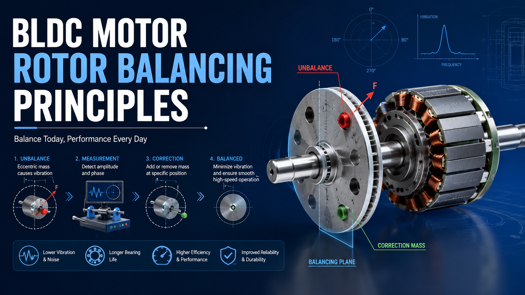
A BLDC Motor rotor spins at high rotational speeds. Even a small mass imbalance can generate significant centrifugal force.
The imbalance force increases proportionally with rotational speed squared.
𝐹=𝑚𝑟𝜔²
Where:
• 𝐹
= centrifugal force
• 𝑚
= unbalanced mass
• 𝑟
= radius from shaft center
• 𝜔
= angular velocity
This means a rotor that performs acceptably at 1,000 RPM may produce severe vibration at 6,000 RPM.
Poor rotor balancing can cause:
• Excessive vibration
• Acoustic noise
• Reduced bearing life
• Shaft deflection
• Increased motor heating
• Encoder instability
• Reduced efficiency
• Premature motor failure
According to the National Institute of Standards and Technology (NIST), vibration-induced mechanical stress significantly reduces rotating equipment reliability in industrial systems.
What Causes Rotor Imbalance in BLDC Motors?
1. Magnet Weight Variation
Permanent magnets may have slight density or dimensional inconsistencies.
Typical imbalance sources include:
• Uneven magnet adhesive thickness
• Magnet chipping
• Different magnetic material densities
• Inconsistent placement angle
This issue becomes more critical in high-pole-count BLDC motors.
2. Shaft Concentricity Errors
Rotor shafts must remain precisely centered.
Common manufacturing problems include:
• Shaft runout
• Machining tolerance deviations
• Improper press fitting
• Bearing seat misalignment
Even 10–20 μm of eccentricity can generate measurable vibration at high RPM.
3. Lamination Stack Tolerance
Rotor laminations may shift during assembly.
Causes include:
• Uneven stamping tolerances
• Burr accumulation
• Improper compression
• Stack skew errors
4. Adhesive Distribution Problems
Excess epoxy or glue near one side of the rotor creates uneven mass distribution.
This is especially common in:
• Outer rotor BLDC motors
• High-speed spindle motors
• Compact servo motors
Static vs Dynamic Balancing
Rotor balancing generally falls into two categories.
Static Balancing
Static balancing corrects imbalance in a single plane.
The rotor is allowed to rotate freely. The heaviest side naturally settles downward.
Suitable For:
• Low-speed motors
• Short rotor designs
• Simple fan motors
Limitations:
• Cannot correct axial imbalance
• Insufficient for high-speed industrial BLDC motors
Dynamic Balancing
Dynamic balancing corrects imbalance in multiple planes while the rotor rotates.
Industrial balancing machines measure:
• Vibration amplitude
• Phase angle
• Imbalance location
Dynamic balancing is required for:
• Servo motors
• High-speed BLDC motors
• Precision automation systems
• EV traction motors
Most industrial BLDC motors above 3,000 RPM require dynamic balancing.
Common Rotor Balancing Standards
ISO 21940 Balancing Standard
The globally recognized balancing standard is ISO 21940.
Formerly known as ISO 1940.
The standard defines balance quality grades.
Typical Balancing Grades
| Balance Grade | Typical Application | Rotor Quality |
|---|---|---|
| G40 | Agricultural machinery | Low precision |
| G16 | Large industrial fans | Moderate |
| G6.3 | Standard industrial motors | Common industrial grade |
| G2.5 | Servo motors | Precision |
| G1.0 | High-speed spindle motors | Very high precision |
| G0.4 | Aerospace systems | Ultra precision |
According to ISO 21940 published by the International Organization for Standardization, lower G values indicate tighter balancing tolerances.
How BLDC Rotor Balancing Is Performed?
Step 1: Initial Rotor Inspection
Engineers first inspect:
• Shaft straightness
• Magnet bonding
• Rotor concentricity
• Bearing surfaces
• Lamination condition
Typical inspection tools include:
• Dial indicators
• Laser runout systems
• Coordinate measuring machines (CMM)
Step 2: Mounting on Balancing Machine
The rotor is mounted onto a balancing machine.
Sensors measure:
• Vibration magnitude
• Rotational phase
• Imbalance location
Modern systems use:
• Piezoelectric accelerometers
• Optical tachometers
• DSP vibration analysis
Step 3: Measure Initial Imbalance
The machine calculates imbalance in:
• g·mm
• oz·in
• mg·mm
Typical industrial rotor imbalance ranges:
| Motor Type | Initial Imbalance |
|---|---|
| Small BLDC motor | 5–50 mg·mm |
| Industrial servo motor | 20–200 mg·mm |
| EV traction motor | 100–1000 mg·mm |
Step 4: Correct the Imbalance
Engineers remove or add material.
Material Removal Methods
• CNC drilling
• Milling
• Grinding
• Laser trimming
Material Addition Methods
• Balancing putty
• Epoxy compensation
• Balancing clips
Material removal is more common in precision BLDC motors.
Step 5: Verification Run
After correction, the rotor undergoes final verification.
Target residual imbalance depends on:
• Rotor mass
• Diameter
• Operating speed
• Application class
Residual Imbalance Formula
Residual imbalance tolerance can be estimated using ISO balancing equations.
𝑈𝑝𝑒𝑟=9549𝐺𝑚/𝑛
Where:
• 𝑈𝑝𝑒r
= permissible residual imbalance
• 𝐺
= balance quality grade
• 𝑚
= rotor mass
• 𝑛
= RPM
This formula helps engineers determine acceptable imbalance levels.
Rotor Balancing Methods Used in Modern BLDC Motors
Single-Plane Balancing
Used for:
• Thin rotors
• Cooling fans
• Compact drone motors
Advantages:
• Lower cost
• Faster balancing
Limitations:
• Reduced precision
Two-Plane Dynamic Balancing
The industry standard for industrial BLDC motors.
Corrects imbalance at:
• Front balancing plane
• Rear balancing plane
Essential for:
• Servo motors
• CNC spindle motors
• Robotics actuators
Automatic Balancing Systems
Advanced production lines use automated balancing stations integrated with:
• CNC systems
• AI-based vibration analysis
• Machine vision
These systems improve repeatability and reduce labor variability.
Typical Vibration Levels for BLDC Motors
Recommended RMS Velocity Levels
| Condition | RMS Velocity |
|---|---|
| Excellent | < 0.7 mm/s |
| Good | 0.7–1.8 mm/s |
| Acceptable | 1.8–4.5 mm/s |
| Excessive | > 4.5 mm/s |
According to vibration guidelines from the International Electrotechnical Commission and industrial rotating machinery studies, vibration above 4.5 mm/s often indicates balancing or bearing issues.
Engineering Challenges in Rotor Balancing
High-Speed BLDC Motors
At speeds above 20,000 RPM:
• Small imbalance becomes critical
• Thermal expansion affects balance
• Magnetic forces influence rotor dynamics
High-speed balancing often requires:
• Vacuum balancing chambers
• Thermal compensation
• Precision spindle balancing systems
Outer Rotor BLDC Motors
Outer rotor designs are more difficult to balance because:
• Rotating mass is farther from center
• Larger moment of inertia
• Magnet positioning tolerance becomes critical
Multi-Pole Rotor Complexity
More poles increase balancing complexity.
Example:
• 2-pole motor → simpler mass symmetry
• 14-pole motor → higher assembly sensitivity
Common Rotor Balancing Problems and Solutions
| Problem | Possible Cause | Recommended Solution |
|---|---|---|
| Excessive vibration | Rotor imbalance | Dynamic rebalancing |
| High acoustic noise | Uneven magnet placement | Reposition magnets |
| Bearing overheating | Shaft eccentricity | Correct shaft alignment |
| Encoder instability | Rotor wobble | Improve balancing tolerance |
| Reduced efficiency | Mechanical drag | Reduce imbalance force |
| Premature bearing failure | High vibration | Achieve lower G grade |
Common Engineering Mistakes
Ignoring Balance at Final Assembly
Balancing the rotor alone is insufficient.
Final balancing should include:
• Shaft
• Magnets
• Cooling fan
• Encoder hub
• Coupling components
Using Static Balancing for High-Speed Motors
Static balancing cannot correct couple imbalance.
High-speed BLDC motors require dynamic balancing.
Over-Removing Material
Aggressive drilling weakens rotor structural integrity.
This may cause:
• Rotor cracking
• Stress concentration
• Fatigue failure
Ignoring Thermal Effects
Rotor balance can shift during operation because of:
• Thermal growth
• Magnet expansion
• Adhesive softening
Testing at operating temperature improves accuracy.
Practical Design Recommendations
Recommended Balancing Grades by Application
| Application | Recommended Grade |
|---|---|
| Household appliances | G6.3 |
| Industrial automation | G2.5–G6.3 |
| CNC spindle motors | G1.0–G2.5 |
| Medical equipment | G1.0 |
| EV drive systems | G2.5 |
| Aerospace motors | G0.4–G1.0 |
How Rotor Balancing Improves Motor Performance?
1. Bearing Life
Bearing life increases significantly when vibration decreases.
According to research from the Massachusetts Institute of Technology and industrial rotating machinery studies, vibration reduction substantially extends rolling bearing service intervals.
2. Energy Efficiency
Lower vibration reduces:
• Friction losses
• Mechanical drag
• Resonance energy loss
Balanced BLDC motors typically demonstrate improved efficiency consistency at high speed.
3. Acoustic Performance
Noise reduction is critical for:
• Medical devices
• Consumer electronics
• Robotics
• HVAC systems
Rotor balancing is one of the most effective methods for lowering tonal vibration noise.
4. Precision Motion Control
Servo systems require:
• Stable torque
• Low vibration
• Accurate encoder feedback
Poor rotor balance negatively affects positioning accuracy.
BLDC Motor Rotor Balancing in Industrial Applications
Robotics
Collaborative robots require:
• Low vibration
• Smooth torque output
• Quiet operation
Dynamic balancing improves robotic arm precision.
Electric Vehicles
EV motors operate at:
• High RPM
• Wide thermal range
• Rapid acceleration cycles
Rotor balancing becomes essential for:
• NVH reduction
• Bearing durability
• Passenger comfort
Medical Equipment
Medical systems require:
• Ultra-low vibration
• Minimal noise
• Stable rotational accuracy
Applications include:
• Surgical tools
• Centrifuges
• Diagnostic systems
UNITED MOTION INC. Rotor Engineering Approach
UNITED MOTION INC. develops BLDC Motor solutions focused on:
• High-precision rotor assembly
• Dynamic balancing optimization
• Low-vibration motion control
• Industrial-grade reliability
• Custom motor engineering
The company combines precision machining, advanced magnetic circuit design, and strict quality control processes to improve rotor stability in demanding industrial applications.
As a professional electric motor manufacturer and custom motion control supplier, UNITED MOTION INC. supports applications including:
• Industrial automation
• Robotics
• Solar tracking systems
• Smart storage systems
• Medical devices
• Servo-driven equipment
FAQ
What is rotor balancing in a BLDC Motor?
Rotor balancing is the process of correcting uneven mass distribution in the rotating assembly to reduce vibration and improve motor performance.
Why is rotor balancing important?
Proper balancing reduces:
• Bearing wear
• Noise
• Vibration
• Energy loss
• Mechanical stress
It also improves reliability and lifespan.
What balancing grade is used for servo motors?
Servo motors commonly use G2.5 or better balancing grades according to ISO 21940 standards.
What causes rotor imbalance?
Common causes include:
• Uneven magnet placement
• Shaft eccentricity
• Adhesive inconsistency
• Machining tolerance errors
• Lamination stack deviation
What is the difference between static and dynamic balancing?
Static balancing corrects imbalance in one plane, while dynamic balancing corrects imbalance in multiple planes during rotation.
Can poor rotor balancing damage bearings?
Yes. Excessive vibration increases bearing load and accelerates fatigue failure.
What tools are used for rotor balancing?
Typical equipment includes:
• Dynamic balancing machines
• Accelerometers
• Optical tachometers
• Laser measurement systems