
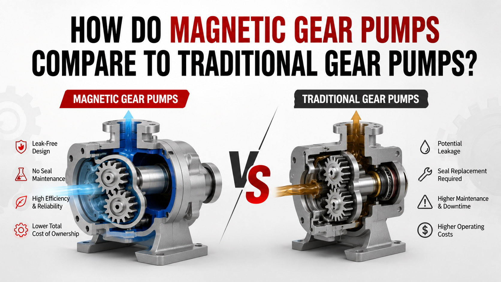
A magnetic gear pump uses a magnetic coupling to transmit motor torque through a stationary containment barrier, eliminating the rotating shaft seal, while a traditional gear pump normally transfers torque through a mechanical shaft and therefore requires a dynamic seal or other shaft-sealing arrangement. The pumping principle remains fundamentally similar: meshing gears create expanding cavities at the inlet, transport fluid through the gear-to-housing clearance, and displace it at the outlet.
The primary engineering advantage of a magnetic gear pump is fluid containment and reduced seal-related maintenance, whereas the traditional gear pump generally offers a simpler mechanical architecture, lower initial cost, and fewer components between the motor and pumping elements. Therefore, magnetic drive is particularly attractive when leakage, contamination, fluid loss, or maintenance access is a major concern; conventional gear pumps remain highly competitive for cost-sensitive hydraulic and industrial applications.
What Is a Magnetic Gear Pump?
A magnetic gear pump is a positive-displacement gear pump in which the motor does not mechanically penetrate the wetted pump chamber. Instead, an external magnet assembly transfers torque through a non-magnetic containment shell to an internal magnet connected to the driving gear.
The result is a sealless or hermetically separated drive arrangement. Because there is no rotating shaft passing through the pressure boundary, the conventional dynamic shaft seal—the component commonly associated with wear and leakage—is eliminated. A 2004 World Pumps engineering review of magnetically driven gear pumps identified the absence of dynamic seals, compact construction, smooth flow, and repeatable flow characteristics as major advantages.
This does not mean that every magnetic gear pump is literally leak-proof under every failure condition. Static O-rings, the containment shell, pump housing, and other pressure-boundary components must still be correctly selected for the fluid, pressure, and temperature.
How Does a Traditional Gear Pump Work?
A traditional gear pump normally uses a directly driven shaft connected to the driving gear. As the gears rotate, tooth spaces on the suction side create expanding volumes that draw fluid into the pump. The fluid is then carried around the outer circumference of the gears before being forced toward the discharge port as the teeth re-mesh.
Because the gear teeth and housing have small clearances, some fluid inevitably leaks internally from the high-pressure side toward the low-pressure side. As pressure differential increases, leakage generally increases, reducing volumetric efficiency. Research from the University of Modena and Reggio Emilia published by SAE in 2009 specifically investigated the relationship between operating speed, delivery pressure, and volumetric efficiency in external gear pumps.
A 2026 study published in Actuators further confirmed that internal leakage, pressure-induced deformation, wear, friction, and geometric effects can significantly influence external gear-pump volumetric efficiency, particularly under high-pressure conditions. The study was published January 15, 2026, by researchers from Pukyong National University.
Magnetic Gear Pump vs Traditional Gear Pump
| Engineering Factor | Magnetic Gear Pump | Traditional Gear Pump |
| Torque transmission | Magnetic coupling | Mechanical shaft |
| Dynamic shaft seal | Not required | Normally required |
| External leakage risk | Very low when properly designed | Higher because of shaft seal |
| Mechanical complexity | Higher magnetic-drive complexity | Simpler |
| Initial cost | Generally higher | Generally lower |
| Seal maintenance | Greatly reduced | Periodic inspection/replacement |
| Dry-running tolerance | Usually limited | Application dependent |
| Fluid containment | Excellent | Dependent on shaft-seal condition |
| Pressure capability | Design-dependent | Generally broad |
| Contaminated fluid tolerance | Often limited by internal bearings | Application-dependent |
| OEM integration | Excellent for compact sealed systems | Excellent for conventional drives |
| Best use case | Leak-sensitive fluids and compact equipment | Cost-sensitive industrial pumping |
The comparison should therefore not be reduced to “magnetic is better.” The correct engineering question is which failure mode matters most in the application.
Step-by-Step: How the Two Designs Differ
1. Torque Transmission
In a conventional gear pump, motor torque passes directly through the shaft into the driving gear.
In a magnetic gear pump, torque crosses the containment barrier through a magnetic field. The magnetic coupling must therefore be sized for the required shaft torque.
For a positive-displacement pump, a useful first-order relationship is:
T ≈ Δp × Vd / (2π × ηm)
where:
T = required pump torque
Δp = differential pressure
Vd = displacement per revolution
ηm = mechanical efficiency
If the required torque approaches the magnetic coupling’s maximum transferable torque, the coupling can decouple or “slip,” depending on its design.
2. Leakage Control
This is usually the most important difference.
A traditional pump has a rotating shaft crossing the pressure boundary, so the seal must accommodate relative motion while maintaining containment.
A magnetic gear pump separates the motor-side rotating assembly from the wetted gear assembly using a stationary containment barrier. Hydraulic Institute guidance published in Pumps & Systems in 2017 describes magnetic-drive pumps as a type of sealless pump using permanent magnets to drive an internal rotating assembly through a containment shell.
For toxic, corrosive, expensive, or high-purity liquids, this distinction can be more important than a small difference in pump efficiency.
3. Efficiency
It is incorrect to assume that eliminating the mechanical seal automatically makes a magnetic gear pump more energy efficient.
Both designs still experience:
- gear meshing losses
- bearing friction
- viscous losses
- internal leakage
- fluid shear
- magnetic coupling losses
- motor losses
External gear-pump efficiency is strongly affected by pressure, speed, viscosity, and clearance. A 2012 SAE study by Milwaukee School of Engineering researchers experimentally evaluated volumetric, mechanical, and overall efficiency under different operating and lubrication conditions.
Magnetic-drive systems also introduce additional design considerations, including magnetic coupling capacity and potential thermal losses associated with the containment structure.
Typical Engineering Selection Ranges
The actual specification must always come from the pump manufacturer’s performance curve, but small OEM magnetic gear pumps can operate in relatively low-flow, high-pressure regimes.
For example, Iwaki’s MDG magnetic-drive gear-pump series lists capacities up to approximately 14–17 L/min, pressure capability up to 87 psi, and liquid temperatures up to 95°C, demonstrating the type of operating envelope available in compact magnetic gear-pump designs.
Traditional external gear pumps can cover much wider industrial ranges, particularly in hydraulic applications, because the direct mechanical drive is not constrained by magnetic coupling torque capacity.
The correct selection parameters should include:
- Flow rate, Q
- Differential pressure, Δp
- Fluid viscosity
- Fluid temperature
- Maximum rotational speed
- Required motor torque
- Material compatibility
- Seal or containment requirements
- Allowable leakage
- Duty cycle
Common Problems and Troubleshooting
| Symptom | Magnetic Gear Pump Possible Cause | Traditional Gear Pump Possible Cause | Engineering Check |
| Low flow | Magnetic decoupling, wear, internal leakage | Gear wear, seal leakage, excessive clearance | Measure rpm, pressure and actual flow |
| Motor runs but pump stops | Coupling overload/decoupling | Shaft or gear failure | Check pump torque and shaft condition |
| Excessive temperature | Dry running, inadequate fluid cooling, eddy-current losses | Bearing friction, seal friction, low lubrication | Check fluid temperature and lubrication |
| External leakage | Static O-ring or housing failure | Mechanical shaft seal failure | Inspect pressure boundary |
| Noisy operation | Cavitation, bearing wear, magnetic issues | Cavitation, gear meshing, bearing wear | Verify inlet pressure and viscosity |
| Reduced pressure | Internal gear leakage or wear | Gear/side-clearance leakage | Check clearances and differential pressure |
One particularly important failure mechanism is dry running. In many magnetic gear pumps, internal bearings depend on the pumped fluid for lubrication and cooling. A 2023 failure investigation from Universiti Teknikal Malaysia Melaka found that contamination and blocked lubrication/cooling passages contributed to failure of magnetic-drive sealless pumps.
When Should Engineers Choose a Magnetic Gear Pump?
Choose a magnetic gear pump when leak prevention, fluid isolation, compact integration, or reduced seal maintenance has a higher economic value than minimum purchase price.
Typical applications include:
- Chemical dosing
- Laboratory equipment
- Medical equipment
- Fuel-cell systems
- Inkjet and printing systems
- Pharmaceutical equipment
- Corrosive-fluid handling
- High-purity fluid systems
- OEM fluid-control modules
The 2004 World Pumps review specifically identified OEM applications such as inkjet printing, fuel cells, and hemodialysis as suitable environments for magnetically coupled gear pumps because of their compact construction and repeatable flow characteristics.
When Is a Traditional Gear Pump Better?
A conventional gear pump is usually the better choice when:
Initial cost is the dominant factor.
Leakage risk is manageable.
The fluid is compatible with a conventional shaft seal.
Direct mechanical power transmission is preferred.
High pressure and torque requirements exceed practical magnetic-coupling limits.
The system already has established seal-maintenance procedures.
Traditional gear pumps remain attractive because their mechanical architecture is straightforward, well understood, and economical to manufacture.
Common Engineering Mistakes
Mistake 1: Selecting Only by Flow Rate
Two pumps can provide the same nominal flow but have very different pressure, viscosity, speed, and torque requirements.
Mistake 2: Ignoring Viscosity
Gear pumps are often selected for viscous fluids, but viscosity strongly affects suction behavior, friction, power consumption, and internal leakage.
Mistake 3: Assuming “Sealless” Means Maintenance-Free
The absence of a shaft seal does not eliminate bearings, O-rings, containment components, magnets, or gear wear.
Mistake 4: Ignoring Magnetic Coupling Torque
The magnetic coupling must be sized against the maximum operating torque, including transient loads and startup conditions.
Mistake 5: Running Without Adequate Fluid
Dry running can rapidly increase bearing temperature and wear, particularly when the pumped fluid provides internal lubrication.
Final Engineering Verdict
Magnetic gear pumps are primarily a containment and reliability solution, while traditional gear pumps are primarily a simple and economical mechanical pumping solution.
For a clean, conventional industrial fluid where leakage can be controlled and maintenance is acceptable, a traditional gear pump can provide an excellent cost-to-performance ratio. When the application involves corrosive, hazardous, expensive, sterile, or contamination-sensitive fluids, the elimination of the dynamic shaft seal can make a magnetic gear pump substantially more attractive over the complete equipment life cycle.
For system designers, the best decision is therefore not based on pump type alone; it should be made from the combined requirements of flow × pressure × viscosity × temperature × speed × torque × leakage tolerance × maintenance strategy.
FAQ
Are magnetic gear pumps more reliable than traditional gear pumps?
They can be more reliable in applications where shaft-seal leakage is a major failure mode because the magnetic coupling eliminates the rotating shaft seal, but reliability still depends on bearings, fluid cleanliness, thermal management, magnetic coupling capacity, and correct operating conditions.
Do magnetic gear pumps have zero leakage?
A properly designed magnetic gear pump eliminates the normal rotating shaft leakage path, but the entire pressure boundary still depends on static seals, the containment barrier, housing, and material compatibility.
Are magnetic gear pumps more efficient?
Not necessarily. Magnetic coupling introduces additional design losses, while conventional gear pumps have shaft-seal, bearing, meshing, and leakage losses. Efficiency must be compared at the actual flow, pressure, viscosity, speed, and temperature.
Can a magnetic gear pump run dry?
Generally, dry running should not be assumed to be acceptable. Many designs depend on the pumped fluid for lubrication and cooling of internal components.
What is the biggest advantage of a Magnetic Gear Pump?
The biggest advantage is elimination of the rotating shaft seal, which substantially reduces the primary external leakage path and can simplify maintenance in leak-sensitive applications.
What is the biggest disadvantage?
The main disadvantages are higher system complexity and cost, magnetic coupling torque limitations, sensitivity to operating conditions, and the need to carefully manage internal lubrication and heat.
Related blog: What is the Main Principle behind a Magnetic Gear Pump?