
Quick Answer
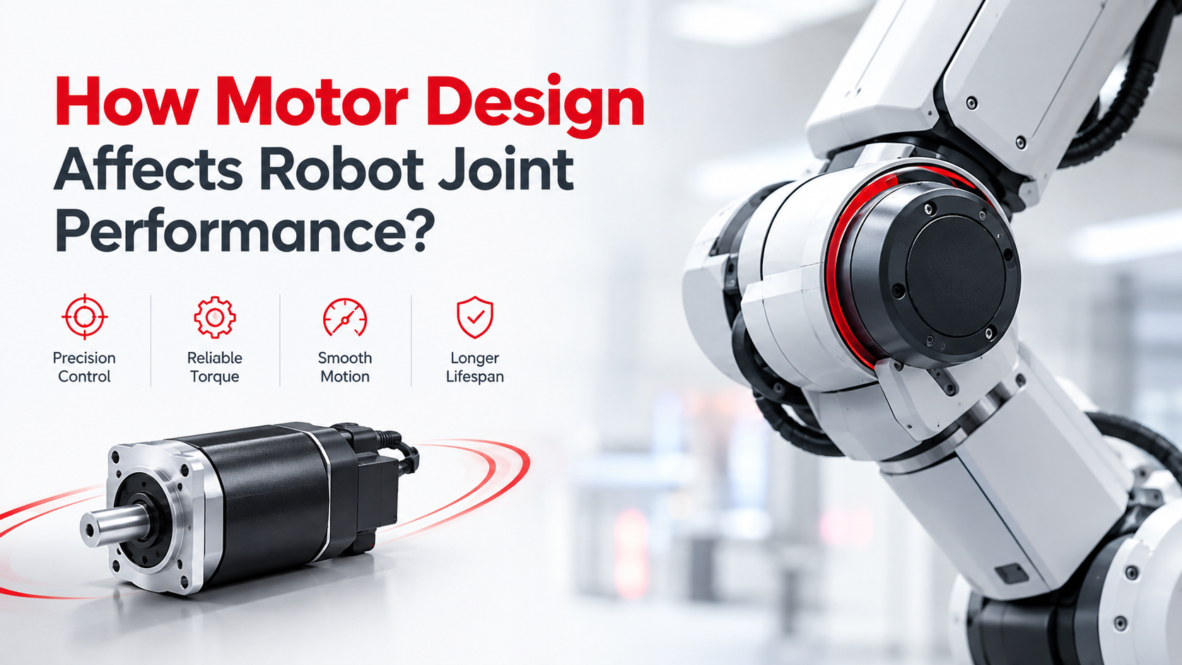
Motor design directly affects the torque, speed, acceleration, positioning accuracy, efficiency, thermal performance, noise, and service life of a robot joint. For robotic applications, the motor should not be selected only according to rated power; engineers need to evaluate the motor’s torque constant, winding configuration, rotor inertia, operating speed, gear ratio, feedback system, thermal capacity, and control requirements as part of a complete actuator system.
A properly designed robotic joint commonly combines a BLDC motor, gearbox, encoder or Hall sensor, and motor driver to achieve the required combination of torque density, dynamic response, positioning accuracy, and operating reliability. United Motion Inc. provides customizable BLDC motors from 28 mm to 110 mm, with options including gearboxes, Hall sensors, encoders, integrated drivers, and customized voltage, winding, shaft, and mounting configurations.
Why Motor Design Matters in Robot Joints?
A robot joint is an integrated electromechanical system rather than simply an electric motor.
The motor generates electromagnetic torque, the gearbox converts motor speed into usable output torque, the feedback device provides rotor or joint position information, and the driver controls current and speed according to the motion command.
The fundamental mechanical relationship is:
T = J × α
where:
- T = acceleration torque, N·m
- J = rotational inertia, kg·m²
- α = angular acceleration, rad/s²
The motor must also overcome load torque and friction:
T_motor ≥ T_load + T_acceleration + T_friction
Therefore, two motors with the same rated power can produce very different robot-joint performance if they have different torque constants, rotor inertia, winding configurations, operating speeds, or gearbox combinations.
For robotic OEMs, this is one of the most important distinctions between motor selection and motor system design.
Motor Torque Density Determines Joint Capability
For compact robots, available installation space is usually limited, which makes torque density an important motor-selection parameter.
Torque density can be considered in terms of:
Torque per unit mass
or
Torque per unit volume
A motor with higher torque density can provide the required joint torque without unnecessarily increasing actuator size and weight.
This is particularly important for:
- Robotic arms
- Humanoid robots
- Quadruped robots
- Collaborative robots
- Mobile robots
- Robotic grippers
- AGV steering mechanisms
Motor torque is strongly influenced by the electromagnetic design, including magnet strength, air-gap design, winding configuration, stator geometry, active stack length, and operating current.
For a BLDC motor, a simplified relationship is:
T ≈ Kt × I
where:
- T = motor torque
- Kt = torque constant
- I = motor current
This means that increasing motor current can increase torque, but continuous operation is ultimately limited by winding temperature, magnetic characteristics, driver capability, and mechanical limitations.
Motor Speed and Gear Ratio Must Be Matched
Robot joints generally require relatively low output speed but relatively high torque, while electric motors can operate efficiently at much higher rotational speeds.
A gearbox therefore becomes an important part of many robotic actuator designs.
For a reduction gearbox:
T_output ≈ T_motor × N × η
where:
- T_output = gearbox output torque
- T_motor = motor torque
- N = reduction ratio
- η = gearbox efficiency
Output speed is approximately:
RPM_output = RPM_motor / N
For example, if a BLDC motor operates at 4,000 rpm and is connected to a 20:1 gearbox, the theoretical output speed is approximately:
4,000 ÷ 20 = 200 rpm
The gearbox increases available torque while reducing output speed.
However, selecting a higher gear ratio is not always better. Increasing the ratio can also influence:
- Backdrivability
- Mechanical efficiency
- Gearbox friction
- Backlash
- Reflected inertia
- Dynamic response
Therefore, the motor and gearbox should be selected as a matched combination rather than independently.
Rotor Inertia Affects Robot Joint Acceleration
One frequently overlooked parameter in robotic motor selection is rotor inertia.
When a robot joint accelerates, the motor must accelerate its own rotor in addition to the mechanical load connected to the joint.
The acceleration torque can be expressed as:
T = J × α
For example, if the effective rotational inertia is 0.08 kg·m² and the required acceleration is 10 rad/s²:
T = 0.08 × 10 = 0.8 N·m
This 0.8 N·m represents the acceleration torque required for that inertia alone.
A high-inertia motor can therefore require additional torque during rapid acceleration and deceleration, while a lower-inertia motor can respond more quickly when the application requires frequent speed changes.
This makes rotor inertia particularly important for:
- High-speed robotic arms
- Humanoid joints
- Pick-and-place robots
- Dynamic mobile robots
- Repetitive positioning systems
Common mistake: selecting the motor only according to maximum torque while ignoring rotor inertia and acceleration requirements.
Torque Ripple Affects Robot Motion Smoothness
For precision robot joints, torque quality is just as important as torque quantity.
Torque ripple can produce:
- Speed fluctuation
- Vibration
- Audible noise
- Position oscillation
- Mechanical resonance
- Reduced low-speed smoothness
BLDC motor torque characteristics are affected by electromagnetic design and commutation strategy.
Traditional six-step commutation is relatively simple and cost-effective, while FOC-based control can provide smoother current control and improved low-speed operation when the motor, driver, and feedback system are properly matched.
For robotic applications where smooth motion is important, engineers should consider:
Motor electromagnetic design + commutation method + feedback + controller tuning
rather than evaluating the motor alone.
Feedback Selection Determines Control Performance
A robot joint normally requires information about motor position, speed, or both.
Common feedback configurations include:
| Feedback | Typical application | Main characteristic |
| Sensorless | Cost-sensitive systems | Simple architecture |
| Hall sensor | BLDC commutation | Economical rotor-position feedback |
| Incremental encoder | Position and speed control | Higher resolution |
| Absolute encoder | Precision positioning | Position available without conventional homing |
For many BLDC motor applications, Hall sensors provide the basic rotor-position information required for electronic commutation.
For higher-precision robotic applications, an encoder can provide substantially more position information to the controller.
United Motion Inc. supports BLDC motors with Hall sensors and encoder options, allowing the feedback configuration to be selected according to the requirements of the robotic actuator.
Thermal Design Determines Continuous Joint Performance
A motor may produce a high peak torque for a short period, but continuous robot operation is determined largely by thermal performance.
Copper winding loss can be approximated by:
P_cu = I²R
where:
- P_cu = copper loss
- I = winding current
- R = winding resistance
This relationship is particularly important because copper loss increases with the square of current.
For example, if current increases from 5 A to 10 A:
P₂ / P₁ = 10² / 5² = 4
The copper loss becomes approximately four times higher, assuming resistance remains constant.
Therefore, engineers should distinguish between:
- Peak torque
- Continuous torque
- Peak current
- Continuous current
- Duty cycle
- Ambient temperature
- Cooling conditions
A motor that meets the peak torque requirement may still be unsuitable if it cannot continuously dissipate the generated heat.
How BLDC Motor Design Supports Robot Applications?
BLDC motors are well suited to many robotic applications because their permanent-magnet rotor construction, electronic commutation, compact size, and controllable speed characteristics allow them to be integrated into relatively compact actuator systems.
United Motion Inc. offers BLDC motor solutions covering approximately 28–110 mm frame sizes, with configurations that can include:
- Hall sensors
- Encoders
- Gearboxes
- Integrated drivers
- Customized voltage
- Customized winding
- Customized shaft
- Customized mounting configuration
This flexibility is particularly useful for OEM robotic applications where the available installation space, torque requirement, voltage, speed, and feedback interface differ from one project to another.
The correct approach is therefore not simply to ask:
“Which BLDC motor has the highest power?”
Instead, engineers should ask:
“Which motor and actuator configuration can provide the required torque, speed, acceleration, control accuracy, and thermal performance within the available mechanical envelope?”
Step-by-Step Robot Joint Motor Selection
Step 1: Calculate the Load Torque
Determine the payload, link weight, gravity torque, friction, and external forces acting on the joint.
Step 2: Calculate Continuous and Peak Torque
Separate normal operating torque from short-duration acceleration, starting, impact, and emergency conditions.
Step 3: Define the Required Speed
Determine continuous speed, maximum speed, acceleration, and deceleration requirements.
Step 4: Select the Gear Ratio
Match the motor speed to the required joint output speed while considering torque multiplication, efficiency, backlash, and dynamic response.
Step 5: Evaluate Motor Inertia
Check whether rotor inertia is compatible with the required acceleration and control response.
Step 6: Select Feedback
Choose Hall sensors, incremental encoders, absolute encoders, or sensorless operation according to the required control precision.
Step 7: Match the Driver
The driver should match the motor’s voltage, current, commutation method, feedback system, and required control mode.
Step 8: Validate Thermal Performance
Test the complete actuator under the actual motion profile and duty cycle instead of validating the motor only under no-load conditions.
Common Robot Joint Motor Problems
| Problem | Possible Cause | Engineering Solution |
| Motor overheating | Excessive current | Reduce load or optimize motor selection |
| Joint torque insufficient | Incorrect motor/gearbox combination | Increase torque capacity or optimize gear ratio |
| Slow acceleration | Excessive rotor or reflected inertia | Select lower-inertia motor or optimize gearing |
| Position fluctuation | Torque ripple or control tuning | Improve motor/control matching |
| Excessive noise | Electromagnetic or mechanical vibration | Optimize motor, driver, and gearbox |
| Poor low-speed movement | Insufficient feedback resolution | Consider encoder feedback |
| Gearbox backlash | Transmission characteristics | Select a lower-backlash gearbox |
| Short motor life | Excessive temperature or overload | Improve thermal design and duty-cycle matching |
Motor Design Parameters for Robot Joints
| Parameter | Why It Matters |
| Rated torque | Determines normal operating capability |
| Peak torque | Determines short-duration acceleration capability |
| Rated speed | Determines operating point |
| Torque constant | Determines torque generated per ampere |
| Rotor inertia | Influences acceleration and dynamic response |
| Gear ratio | Determines output torque and speed |
| Gearbox efficiency | Determines actual output performance |
| Backlash | Influences positioning accuracy |
| Torque ripple | Influences smoothness and vibration |
| Feedback resolution | Influences position-control performance |
| Winding resistance | Influences copper losses |
| Thermal capacity | Determines continuous operating capability |
| Motor diameter | Affects available electromagnetic torque and installation space |
FAQ
What type of motor is best for a robot joint?
There is no single motor that is suitable for every robot joint. BLDC motors are commonly suitable when the application requires compact size, controllable speed, efficient operation, and integration with sensors, gearboxes, and drivers. The final selection should be based on torque, speed, inertia, duty cycle, feedback, and thermal requirements.
How does motor design affect robot joint performance?
Motor design affects torque density, acceleration, efficiency, torque ripple, thermal performance, noise, and overall actuator size. Winding configuration, rotor design, magnet characteristics, motor dimensions, and feedback configuration all influence the final joint performance.
Why is rotor inertia important for robot joints?
Rotor inertia affects how quickly the motor can accelerate and decelerate. Lower rotor inertia can be advantageous in applications requiring rapid changes in joint speed.
How does gear ratio affect robot joint torque?
A reduction gearbox increases output torque approximately according to the gear ratio while reducing output speed, although actual torque is reduced by gearbox losses.
Are BLDC motors suitable for humanoid robots?
Yes. BLDC motors can be configured with different voltages, windings, feedback devices, gearboxes, and drivers, making them suitable for various robotic actuator architectures.
Should a robot motor be selected based only on power?
No. Rated power alone does not describe the complete actuator performance. Engineers should evaluate torque, speed, acceleration, inertia, gear ratio, feedback, thermal performance, and duty cycle.