
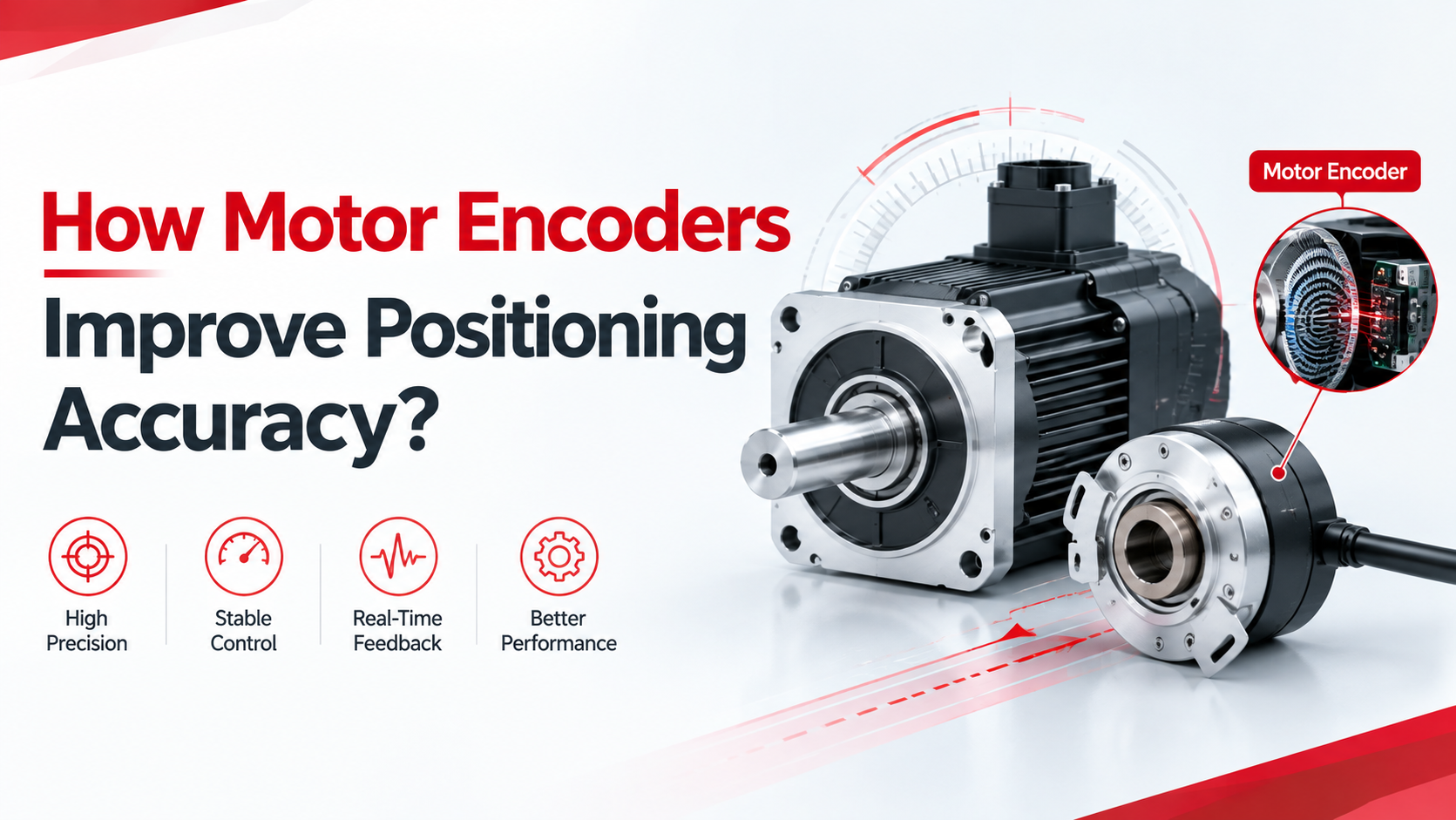
Quick Answer
A motor encoder improves positioning accuracy by continuously measuring the motor shaft’s rotational position and sending feedback signals to the motor controller, allowing the control system to detect position errors and adjust motor operation in real time.
Unlike an open-loop motor system, which estimates movement based on commanded voltage, current, or operating time, an encoder-based closed-loop system can monitor actual shaft movement and respond when the motor deviates from its target position.
The positioning performance depends on several factors, including encoder resolution, signal quality, mounting accuracy, control-loop response, mechanical backlash, and load conditions.
For OEM applications requiring repeatable positioning, smooth low-speed operation, and reliable motion control, selecting the correct motor encoder is just as important as selecting the motor itself.
What Is a Motor Encoder?
A motor encoder is a feedback device installed on or integrated with a motor shaft to measure rotational position, speed, and sometimes direction of rotation.
It converts mechanical movement into electrical signals that can be interpreted by a motor controller or motion control system.
In practical motor applications, an encoder helps the controller determine whether the motor has reached its target position, whether it is rotating at the commanded speed, and whether unexpected movement or positioning errors have occurred.
Common motor encoder technologies include:
- Incremental Encoder: Generates pulses corresponding to shaft rotation and is commonly used for speed measurement and relative positioning.
- Absolute Encoder: Provides a unique position value within its measurement range, allowing the control system to identify the shaft position without relying solely on accumulated movement pulses.
- Optical Encoder: Uses light and a coded disk to detect rotational movement.
- Magnetic Encoder: Uses magnetic sensing technology to detect the position of a rotating magnetic target.
The appropriate encoder depends on positioning requirements, environmental conditions, motor dimensions, controller compatibility, and overall system cost.
How Do Motor Encoders Improve Positioning Accuracy?
Real-Time Position Feedback
The primary advantage of a motor encoder is that it provides actual position feedback rather than relying entirely on estimated motor movement.
In an open-loop system, the controller sends a command to rotate the motor by a specific amount, but it cannot directly confirm whether the shaft has completed the requested movement.
When the motor experiences excessive load, mechanical resistance, or insufficient driving torque, the actual movement may differ from the commanded movement.
An encoder solves this problem by continuously reporting shaft movement, allowing the controller to identify deviations and make corrections.
This is particularly useful for:
- Industrial automation equipment
- Robotic joints
- AGV drive systems
- Medical positioning equipment
- Automated doors
- Packaging machinery
- Precision actuators
Higher Position Resolution
Encoder resolution determines how finely the rotational movement can be measured.
For incremental encoders, resolution is commonly specified in pulses per revolution (PPR) or lines per revolution (LPR), while some manufacturers specify counts per revolution (CPR), depending on the counting convention.
For example, a 1,024 PPR incremental encoder using quadrature decoding can provide 4,096 counts per revolution when all four signal transitions are counted.
This corresponds to approximately 0.088 degrees of nominal shaft movement per count.
| Encoder Resolution | Counts Per Revolution with x4 Decoding | Nominal Angular Increment |
|---|---|---|
| 100 PPR | 400 | 0.9° |
| 256 PPR | 1,024 | 0.352° |
| 500 PPR | 2,000 | 0.18° |
| 1,024 PPR | 4,096 | 0.088° |
| 2,048 PPR | 8,192 | 0.044° |
Higher resolution allows the controller to detect smaller increments of rotational movement, which can improve positioning granularity.
However, higher encoder resolution does not automatically guarantee higher positioning accuracy. Mechanical backlash, installation errors, signal interference, and control-system performance must also be considered.
Better Speed and Direction Control
Most incremental encoders provide two output channels, commonly called Channel A and Channel B, with a phase difference that allows the controller to determine both rotational speed and direction.
This information helps the motor controller regulate acceleration, deceleration, and rotational speed.
For applications requiring frequent starting, stopping, and reversing, encoder feedback helps reduce overshoot and improve motion repeatability.
For example, a robotic actuator that repeatedly moves between two positions needs reliable speed and direction information to achieve consistent movement without excessive vibration or positioning deviation.
Improved Closed-Loop Control
An encoder is an essential feedback component in many closed-loop motor systems.
The controller compares the commanded position with the actual measured position and adjusts the motor’s output according to the detected error.
When properly configured, this process helps compensate for load disturbances, changes in operating conditions, and variations in motor response.
In PMSM and BLDC applications, encoder feedback can also support Field-Oriented Control (FOC), particularly when accurate rotor position information is required for motor commutation and current control.
Incremental Encoder vs. Absolute Encoder
Choosing between incremental and absolute encoders depends primarily on whether the application requires relative movement measurement or direct position identification.
| Comparison | Incremental Encoder | Absolute Encoder |
|---|---|---|
| Position measurement | Relative position | Actual coded position |
| Output | Pulses | Position data or coded signals |
| Position after power loss | Usually requires re-referencing | Retains position information depending on design |
| Resolution | Specified by PPR/CPR | Specified by position bits or steps |
| System complexity | Generally simpler | Generally more complex |
| Cost | Generally lower | Generally higher |
| Typical applications | Speed control, relative positioning | Robotics, positioning stages, precision automation |
An incremental encoder is often suitable for applications where the system can perform a homing operation after startup.
An absolute encoder is preferable when the application needs to identify the shaft position immediately after power restoration without repeating a full homing procedure.
What Factors Affect Motor Encoder Positioning Accuracy?
Even when an encoder has high resolution, the complete motor system may not achieve the expected positioning performance.
Engineers should evaluate the following factors.
| Factor | Effect on Positioning | Engineering Consideration |
|---|---|---|
| Encoder resolution | Determines measurement granularity | Select appropriate PPR or CPR |
| Encoder mounting | Can introduce measurement errors | Ensure concentric and stable installation |
| Signal interference | May cause missed or incorrect pulses | Use suitable shielding and wiring |
| Mechanical backlash | Creates output positioning deviation | Evaluate gearbox backlash |
| Shaft runout | Affects encoder alignment | Control shaft and bearing tolerances |
| Controller response | Influences positioning correction | Optimize control-loop parameters |
| Load variation | Changes motor movement behavior | Check continuous and peak torque |
| Temperature | Can affect mechanical and electrical characteristics | Validate operating temperature range |
One important consideration is the difference between encoder resolution and actual system positioning accuracy.
An encoder may detect very small shaft movements, but if the gearbox has backlash or the mechanical structure has excessive compliance, the final output position can still deviate from the target.
How to Select the Right Motor Encoder?
Step 1: Define Positioning Requirements
Determine the required positioning accuracy, repeatability, operating speed, acceleration, and load conditions before selecting an encoder.
A simple speed-control application may not require the same resolution as a robotic actuator or automated positioning platform.
Step 2: Select Encoder Type
Choose between incremental and absolute feedback based on startup requirements, positioning methods, controller compatibility, and application complexity.
Step 3: Determine Encoder Resolution
Consider the motor’s rotational speed and required positioning granularity.
Higher-resolution encoders provide more feedback information, but the controller must also support the corresponding signal frequency and processing requirements.
Step 4: Check Electrical Compatibility
Verify:
- Supply voltage
- Output signal type
- Channel configuration
- Signal frequency
- Connector type
- Cable length
- Controller compatibility
Common encoder interfaces include incremental A/B/Z signals and digital communication interfaces, depending on encoder architecture.
Step 5: Evaluate Mechanical Integration
Check encoder dimensions, shaft configuration, mounting space, environmental protection, and alignment requirements.
For motors with gearboxes, engineers should also evaluate gearbox backlash and the location of the encoder, since measuring the motor shaft does not necessarily provide direct measurement of the gearbox output shaft.
Step 6: Validate the Complete System
Test positioning repeatability, speed stability, acceleration, deceleration, load response, and performance under different operating temperatures.
Common Motor Encoder Problems and Troubleshooting
| Problem | Possible Cause | Recommended Solution |
|---|---|---|
| Incorrect position feedback | Wiring or signal configuration error | Check A/B channel connections |
| Position drift | Missed pulses or incorrect counting | Check signal integrity and controller settings |
| Unstable speed feedback | Electrical noise | Improve shielding and grounding |
| Incorrect rotation direction | Reversed encoder channels | Verify channel phase relationship |
| Positioning overshoot | Improper control-loop tuning | Adjust motion control parameters |
| Inconsistent output position | Gearbox backlash | Evaluate mechanical transmission |
| No encoder signal | Power supply or wiring failure | Check encoder voltage and connections |
| Position lost after power-off | Incremental encoder without homing | Implement a homing procedure or use an absolute encoder |
Why Encoder Integration Matters for OEM Motor Solutions?
For OEM manufacturers, choosing an encoder should not be an isolated purchasing decision because motor performance depends on the compatibility between the motor, feedback device, controller, and mechanical transmission.
UNITED MOTION INC. provides BLDC motor solutions covering approximately Φ28–Φ110 mm, with customization options including encoder integration, gearboxes, and integrated drivers.
These configurations support different requirements for speed regulation, position feedback, installation dimensions, and motion control.
For example:
BLDC motors with encoders can support closed-loop speed and position control.
Gear motors with encoders combine motor feedback with mechanical speed reduction for applications requiring controlled output movement.
Motors with integrated drivers can simplify electrical integration and reduce external wiring requirements.
Customized motor solutions allow voltage, torque, speed, feedback, and mechanical configurations to be matched to specific OEM applications.
For robotics, AGVs, medical equipment, industrial automation, and other precision motion applications, selecting the correct motor and encoder combination can improve system controllability, repeatability, and integration efficiency.
UNITED MOTION INC. focuses on customized motor solutions designed around actual application requirements rather than selecting motors based on rated power alone.
Common Mistakes When Selecting Motor Encoders
Mistake 1: Choosing the highest encoder resolution available.
Higher resolution is not always necessary, and excessive signal frequency can increase controller processing requirements without improving actual mechanical positioning accuracy.
Mistake 2: Ignoring gearbox backlash.
An encoder installed on the motor shaft measures motor rotation, but mechanical backlash can still cause positioning errors at the gearbox output.
Mistake 3: Overlooking electrical compatibility.
An encoder’s voltage, output type, signal frequency, and communication method must match the motor controller.
Mistake 4: Evaluating the encoder separately from the motor.
Motor torque, speed, inertia, control strategy, and mechanical structure all influence the final positioning performance.
FAQ
1. How does a motor encoder improve positioning accuracy?
A motor encoder measures actual shaft movement and provides feedback to the controller, allowing the system to detect positioning errors and adjust motor operation in real time.
2. What is the difference between an incremental and absolute encoder?
An incremental encoder measures relative movement through pulses, while an absolute encoder provides a unique position value that can identify the shaft position within its measurement range.
3. Does a higher encoder resolution mean better positioning accuracy?
Not necessarily. Higher resolution improves measurement granularity, but actual positioning accuracy also depends on mechanical tolerances, backlash, signal quality, and controller performance.
4. Can a BLDC motor use an encoder?
Yes. BLDC motors can integrate incremental or absolute encoders to provide position and speed feedback for closed-loop control applications.
5. Why does a motor lose positioning accuracy?
Common causes include missed encoder pulses, electrical interference, gearbox backlash, mechanical misalignment, excessive load variation, and incorrect controller tuning.
6. Is an encoder necessary for closed-loop motor control?
An encoder is a common feedback solution for closed-loop motor control, although some systems use other position-sensing technologies, such as resolvers or sensorless estimation methods.
7. Can an encoder be integrated with a gearbox motor?
Yes. Encoders can be installed on the motor shaft or, in certain designs, the gearbox output shaft. The installation location determines which rotational position is directly measured and whether gearbox backlash is included in the feedback measurement.