
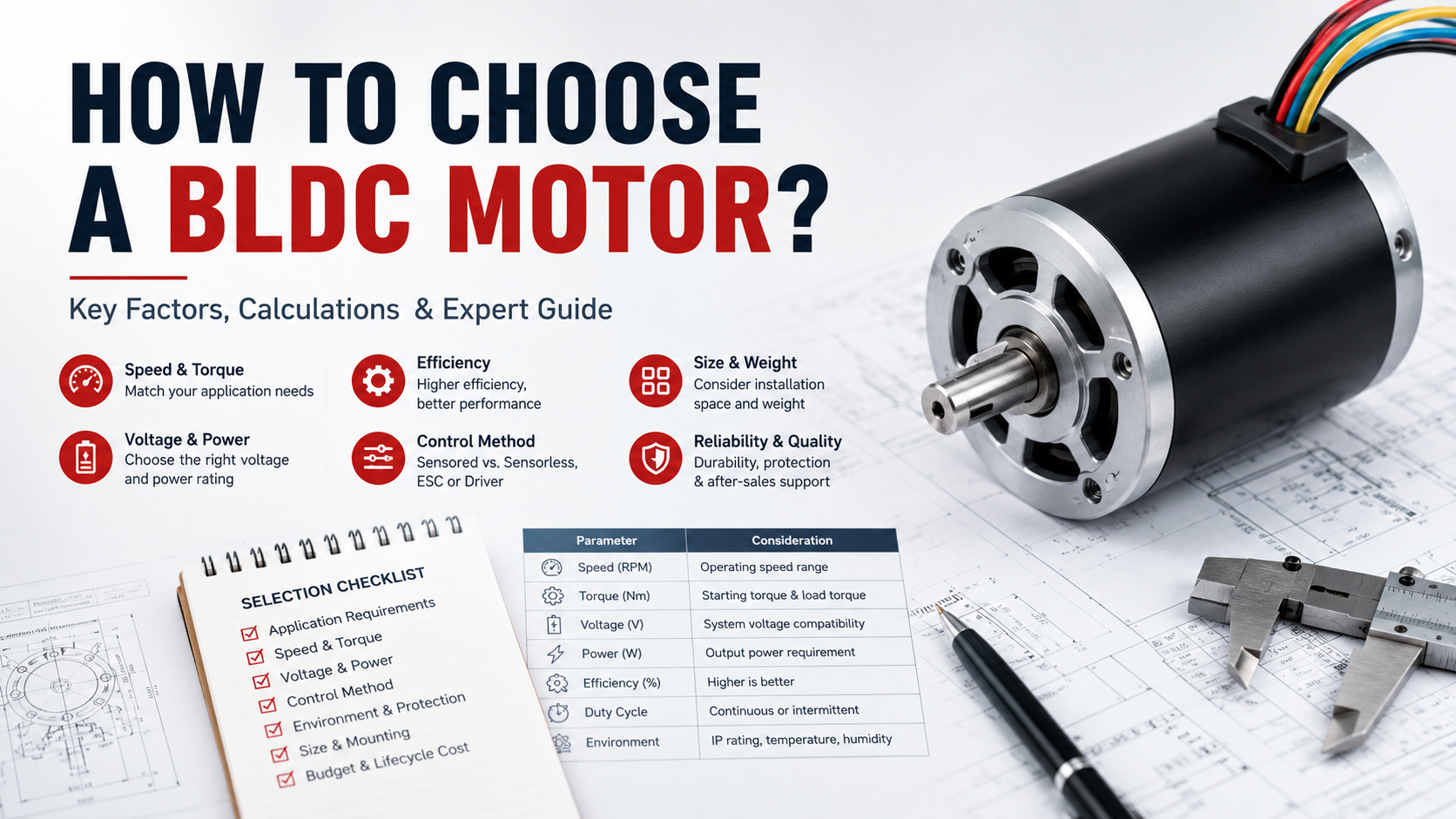
Choosing the correct BLDC motor is not simply a matter of matching voltage and rated power; for industrial automation, robotics, pumps, electric mobility, solar tracking, lawn equipment, and other motion-control applications, the motor must be selected as part of a complete electromechanical system in which torque, speed, acceleration, thermal behavior, controller compatibility, mechanical installation, feedback, and operating environment are considered together.
The U.S. Department of Energy (DOE), in its Energy-Efficient Electric Motor Selection Handbook published in 1996, emphasizes evaluating motor load, speed, efficiency, design characteristics, and operating conditions rather than selecting a motor based only on nameplate power.
Quick Answer: How Do You Choose a BLDC Motor?
To choose the right BLDC motor, follow these seven steps:
Calculate continuous and peak load torque.
Define the required operating speed and maximum RPM.
Calculate mechanical power using torque and speed.
Match motor voltage with the DC power supply and controller.
Select Hall sensors, encoder feedback, or sensorless control.
Check thermal conditions, duty cycle, ambient temperature, and cooling.
Verify mounting dimensions, shaft design, gearbox requirements, and controller compatibility.
A practical selection should also include a safety margin rather than operating continuously at the motor’s absolute rated limit.
Challenge 1: Selecting the Correct Torque
Torque is usually the first engineering parameter that should be established because a motor that reaches the required RPM but cannot continuously produce the required load torque will overheat, lose speed, or stall.
For a rotating load:
T = F × r
where:
T = torque in N·m
F = tangential force in N
r = effective radius in m
Mechanical power can then be estimated as:
P = T × ω
or:
P(kW) = T(N·m) × RPM / 9550
For example, a load requiring 2 N·m at 1,500 RPM requires approximately:
P = 2 × 1500 / 9550 ≈ 0.31 kW
However, selecting a 310 W BLDC motor purely from this calculation would be insufficient because acceleration, transmission losses, temperature, duty cycle, and transient loads must also be considered.
DOE’s motor-selection guidance recommends evaluating the actual load profile and operating point instead of relying solely on the motor nameplate rating. Energy-Efficient Electric Motor Selection Handbook, U.S. Department of Energy, 1996.
Continuous Torque vs. Peak Torque
A BLDC motor specification should distinguish between:
| Parameter | Meaning | Selection Consideration |
| Continuous torque | Torque available continuously within thermal limits | Must meet normal operating load |
| Peak torque | Short-duration torque capability | Must cover acceleration or transient loads |
| Stall torque | Torque near zero speed | Important for starting and positioning |
| Rated torque | Manufacturer-defined operating point | Verify speed and thermal conditions |
Common mistake: selecting a motor based only on peak torque.
For industrial equipment, the continuous torque requirement is generally more important because excessive continuous current increases copper losses and winding temperature.
Challenge 2: Matching Speed and BLDC Motor KV
Speed selection must consider both normal operating RPM and maximum RPM.
A BLDC motor’s KV rating is commonly expressed as RPM per volt under specified no-load conditions. For example, a theoretical 1,000 KV motor supplied with 24 V could approach 24,000 RPM without load, although the actual loaded speed will be lower.
A higher KV generally favors higher speed and lower torque per ampere, while a lower KV motor is normally more suitable for higher torque at lower speed.
For industrial applications, engineers should therefore compare the complete speed-torque curve rather than selecting a motor from KV alone.
Important: motor speed is also affected by winding design, back EMF, load torque, controller strategy, supply voltage, and temperature.
Challenge 3: Choosing the Correct Voltage
Common BLDC motor voltage options include:
12 V
24 V
36 V
48 V
72 V
The correct voltage depends on the available power source, current requirements, insulation system, controller, and application architecture.
For example, at the same 1 kW mechanical power, a 24 V system theoretically requires much more current than a 48 V system before accounting for efficiency and power losses.
Therefore, increasing system voltage can be useful for reducing current and conductor losses, but the motor, controller, connectors, insulation, and power supply must all be designed for the selected voltage.
DOE’s motor-system publications emphasize evaluating the motor and drive as an integrated system rather than optimizing one component independently. U.S. Department of Energy, Motor Systems resources, updated/current program materials.
Challenge 4: Thermal Management and Duty Cycle
One of the most common BLDC motor selection errors is ignoring thermal performance.
Motor losses are converted primarily into heat through mechanisms such as:
- Copper loss
- Iron/core loss
- Mechanical losses
- Switching and inverter losses
- Bearing losses
Copper loss is approximately related to:
Pcu = I²R
This means that increasing current significantly increases winding losses.
A motor rated for a particular torque at 25°C ambient may not provide the same continuous capability in a 50°C enclosure without adequate heat dissipation.
NIST’s NVLAP Efficiency of Electric Motors, published in 2020, provides laboratory accreditation and technical guidance for electric-motor efficiency testing, reinforcing the importance of standardized measurement when comparing motor performance. Timothy W. Rasinski, NIST, 2020.
Thermal Selection Checklist
| Parameter | Typical Engineering Question |
| Ambient temperature | Is the motor operating at 25°C, 40°C, 60°C or higher? |
| Duty cycle | Continuous, intermittent, S2, S3 or variable load? |
| Cooling | Natural convection, forced air or machine-frame conduction? |
| Enclosure | Is heat trapped inside the equipment? |
| Current | Does continuous current remain within the thermal limit? |
| Mounting | Does the mounting structure help dissipate heat? |
Common mistake: comparing two BLDC motors using rated power while ignoring their thermal conditions and duty cycle.
Challenge 5: Hall Sensors, Encoder or Sensorless Control?
A BLDC motor requires electronic commutation, so feedback selection can strongly influence starting behavior, low-speed control, positioning accuracy, and system cost.
Hall Sensor
Hall sensors provide rotor-position information and are commonly used where reliable commutation and controlled low-speed operation are required.
Encoder
An encoder provides higher-resolution position and speed feedback and is useful for robotics, servo-like motion, positioning systems, and applications requiring precise speed regulation.
Sensorless Control
Sensorless BLDC control estimates rotor position using electrical signals such as back EMF. It can reduce wiring and component count, but low-speed starting and near-zero-speed control can be more challenging.
United Motion Inc. provides BLDC motor configurations with Hall sensors, encoder integration, and driver integration according to application requirements.
Challenge 6: Mechanical Size Does Not Equal Motor Capability
A compact motor is attractive when installation space is limited, but the smallest available frame should not automatically be selected.
United Motion Inc.’s BLDC motor portfolio includes frame diameters from 28 mm to 110 mm, covering compact motion systems through higher-power industrial applications.
Important mechanical parameters include:
- Motor diameter
- Motor length
- Shaft diameter and length
- Mounting flange
- Mounting-hole pattern
- Bearing arrangement
- Rotor inertia
- Gearbox interface
For example, the available series include 28 mm, 36 mm, 42 mm, 52 mm, 57 mm, 60 mm, 80 mm, 90 mm, 100 mm and 110 mm BLDC motors.
The correct selection is therefore not simply “smallest motor that fits,” but the smallest motor that can satisfy the complete electrical, thermal, mechanical, and dynamic requirements.
Challenge 7: Do You Need a Gearbox?
If the required output speed is low but output torque is high, a BLDC gear motor can be more practical than directly increasing motor size.
For example, a gearbox with a 10:1 reduction theoretically increases output torque approximately tenfold before accounting for gearbox efficiency, while reducing output speed by approximately ten times.
Gearbox selection should consider:
- Reduction ratio
- Continuous output torque
- Peak output torque
- Gearbox efficiency
- Backlash
- Service life
- Radial and axial loads
- Noise
- Mounting configuration
United Motion Inc. supports gearbox integration, including configurations combining a BLDC motor with a gearbox, encoder, Hall sensors, and controller.
BLDC Motor Selection Comparison
| Requirement | Recommended Consideration |
| Compact installation | Smaller frame BLDC motor |
| High-speed operation | Higher-speed winding / appropriate KV |
| High torque at low speed | Lower KV or gearbox |
| Precise positioning | Encoder feedback |
| Reliable low-speed commutation | Hall sensor |
| Cost-sensitive application | Sensorless control where suitable |
| Battery-powered system | 12/24/36/48/72 V architecture |
| High continuous load | Larger frame and improved thermal design |
| Space-constrained high torque | BLDC motor + gearbox |
A Practical 7-Step BLDC Motor Selection Process
Step 1: Define load torque, including continuous and peak requirements.
Step 2: Define operating RPM, acceleration time, and maximum speed.
Step 3: Calculate mechanical power using torque and speed.
Step 4: Select the system voltage and verify controller compatibility.
Step 5: Determine whether Hall sensors, encoder feedback, or sensorless control is appropriate.
Step 6: Check thermal conditions, duty cycle, ambient temperature, cooling, and enclosure.
Step 7: Verify mechanical dimensions and decide whether a gearbox, brake, or customized shaft configuration is required.
This process is consistent with the broader systems-based approach recommended by the U.S. Department of Energy for motor selection and motor-driven systems.
FAQ: How to Choose a BLDC Motor?
What is the most important parameter when choosing a BLDC motor?
For most applications, the first parameters are continuous torque and operating speed, followed by peak torque, voltage, duty cycle, thermal conditions, feedback, and mechanical dimensions.
How do I calculate BLDC motor power?
Use:
P(kW) = T(N·m) × RPM / 9550
The calculated power should then be evaluated together with efficiency, acceleration, duty cycle, and thermal limitations.
What voltage is best for a BLDC motor?
There is no universally best voltage. Common systems use 12 V, 24 V, 36 V, 48 V, or 72 V, depending on application power, current, battery architecture, and controller requirements.
Do BLDC motors need Hall sensors?
Not always. A BLDC motor can use Hall sensors, an encoder, or sensorless control. Hall sensors are particularly useful when reliable commutation and low-speed operation are important.
Should I choose a BLDC motor with a gearbox?
A gearbox is often appropriate when the application requires low output speed and increased output torque without using a much larger direct-drive motor.
What causes a BLDC motor to overheat?
Typical causes include excessive load torque, excessive current, insufficient cooling, high ambient temperature, incorrect controller settings, bearing problems, or operation beyond the rated duty cycle.
How long can a BLDC motor last?
Service life depends strongly on bearing quality, temperature, load, speed, lubrication, and operating conditions. The absence of brushes eliminates brush wear, but bearings and thermal stress remain important life-limiting factors.