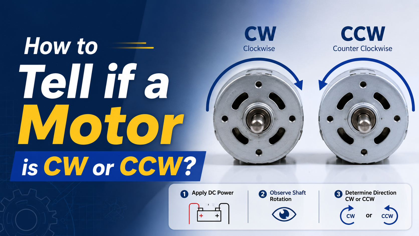
To determine whether a motor is clockwise (CW) or counterclockwise (CCW):
Look at the motor shaft (drive end).
Check the arrow on the motor housing or nameplate.
Review the wiring diagram.
Check phase sequence for three-phase motors.
Perform a safe jog test before connecting the load.
Use the motor driver settings if using BLDC, servo, or stepper motors.
Important: Always confirm from which side the manufacturer defines rotation. Most international standards define rotation when viewed from the drive end (shaft side).
Why Motor Rotation Direction Matters?
Motor rotation direction is not a trivial specification.
Incorrect rotation can cause:
- Pumps to move fluid backward
- Conveyor belts to run in reverse
- Fans to lose efficiency
- Compressors to fail
- Gearboxes to experience mechanical damage
- Automation systems to malfunction
For OEM equipment manufacturers, incorrect motor rotation is among the most common startup commissioning issues.
According to industrial motor commissioning best practices published by the U.S. Department of Energy (DOE), proper motor verification before coupling loads reduces startup errors and prevents unnecessary equipment downtime.
Source: U.S. Department of Energy (DOE), Motor Systems Program, U.S. Department of Energy, updated resources for industrial motor systems.
What Do CW and CCW Mean?
CW = Clockwise
CCW = Counterclockwise
These terms describe shaft rotation when viewed from a specified side.
Standard Reference Direction
Always determine:
Which side are you looking from?
Most international standards use:
Drive End (DE) = Shaft side
If the shaft rotates:
Right = CW
Left = CCW
Many engineers make mistakes because they observe from the rear side.
How Standards Define Motor Rotation?
Rotation direction shall be observed from the drive end (D-end).
The standard also defines terminal markings and phase relationships for AC and DC machines.
Source: IEC 60034-8 (International Electrotechnical Commission), “Rotating Electrical Machines – Terminal Markings and Direction of Rotation,” updated 2025/2026 edition.
Method 1: Check the Arrow Marked on the Motor Housing
The easiest method is locating the directional arrow.
Manufacturers often print:
- CW
- CCW
- Rotation arrow
Common locations:
- Nameplate
- Gearbox housing
- Fan cover
- Driver label
Example:
→ CW
This indicates clockwise rotation when viewed from the specified side.
If no arrow exists, proceed to the next methods.
Method 2: Check the Motor Nameplate
Industrial motors often specify rotation.
Look for terms like:
| Marking | Meaning |
| CW | Clockwise |
| CCW | Counterclockwise |
| REV | Reversible |
| NON-REV | Non-reversible |
Typical examples:
Rotation: CW DE
Meaning:
Clockwise when viewed from drive end.
Another example:
Rotation: Reversible
Meaning:
Direction can be changed electrically.
Method 3: Check the Wiring Diagram
The wiring diagram often tells the entire story.
Three-Phase AC Motors
Most industrial induction motors are reversible.
Swap any two phases.
Example:
Original:
L1 → U
L2 → V
L3 → W
Reverse:
L1 → U
L3 → V
L2 → W
The motor direction reverses immediately.
According to IEC 60034-8, reversing two phases changes rotational direction.
Source: IEC 60034-8, International Electrotechnical Commission, updated 2026.
Single-Phase Motors
Single-phase motors require auxiliary winding reversal.
Examples include:
- PSC motors
- Capacitor start motors
- Capacitor run motors
Manufacturers usually expose reversing wires.
Common wire colors:
- White
- Black
- Red
- Yellow
Always follow the manufacturer’s wiring diagram.
Never guess wire functions.
DC Motors
Permanent magnet DC motors reverse by changing polarity.
Original:
+ → Red
– → Black
Reverse:
+ → Black
– → Red
Direction changes.
BLDC Motors
Brushless DC motors are electronically commutated.
Reverse methods:
Sensorless BLDC
Swap any two phase wires.
Or
Modify controller settings.
Hall Sensor BLDC
Use:
- Driver software
- Controller parameter
- Reverse command
Never randomly swap Hall sensor wires.
Servo Motors
Servo motors are software-controlled.
Direction is changed through:
- Servo drive parameters
- Encoder configuration
- PLC commands
Common parameters:
- DIR = Positive
- DIR = Negative
- Stepper Motors
Reverse direction by changing pulse sequence.
Controller settings often include:
DIR HIGH = CW
DIR LOW = CCW
Or vice versa.
Always verify documentation.
Method 4: Perform a Safe Jog Test
This is the most reliable field method.
Step 1
Disconnect the load.
Remove:
- Couplings
- Belts
- Chains
Never test under full load.
Step 2
Apply power briefly.
Jog duration:
0.5-1 second
Observe rotation.
Step 3
Verify direction.
If incorrect:
Adjust wiring.
Retest.
Method 5: Check the Motor Driver Settings
Modern motors increasingly rely on electronic controls.
Common systems:
- Servo drives
- VFDsBLDC controllers
Look for parameters:
| Parameter | Description |
| DIR | Direction |
| REV | Reverse |
| CW/CCW | Rotation mode |
| Positive direction | Forward direction |
Many commissioning errors occur here.
Motor Rotation Identification by Motor Type
| Motor Type | How To Identify | How To Reverse |
| Three-phase induction motor | Phase sequence | Swap any two phases |
| Single-phase AC motor | Wiring diagram | Reverse auxiliary winding |
| PMDC motor | Polarity | Swap positive and negative |
| BLDC motor | Controller settings | Change software or phase sequence |
| Servo motor | Drive parameters | Software configuration |
| Stepper motor | Pulse sequence | Reverse DIR signal |
Step-by-Step Field Inspection Procedure
Step 1: Read the nameplate
Check:
- Rotation arrow
- CW/CCW label
- Reversible indication
Step 2: Locate shaft side
Identify:
Drive End (DE)
Non-Drive End (NDE)
Observe from the shaft side.
Step 3: Verify wiring
Review:
- Terminal box
- Driver settings
- Wiring diagram
Step 4: Disconnect mechanical load
Remove:
- Belts
- Chains
- Couplings
Step 5: Jog test
Momentarily energize.
Observe carefully.
Step 6: Record the result
Document:
- Direction
- Wiring configuration
- Controller settings
This simplifies future maintenance.
Common Engineering Mistakes
Mistake 1: Looking from the wrong side
Very common.
Looking from the rear reverses your interpretation.
Always verify the observation side.
Mistake 2: Assuming all motors are CW
No universal rule exists.
Every manufacturer differs.
Always verify.
Mistake 3: Connecting loads before testing
This can damage:
- Pumps
- Gearboxes
- Conveyor systems
Always test unloaded.
Mistake 4: Randomly swapping wires
Especially dangerous for:
Servo motors
Hall sensor BLDC motors
Incorrect rewiring may damage the driver.
Mistake 5: Ignoring VFD settings
VFD parameters often override physical wiring.
Check software first.
Troubleshooting Table
Motor Rotates Opposite Direction
| Problem | Possible Cause | Solution |
| Conveyor moves backward | Wrong phase sequence | Swap two phases |
| Fan airflow reversed | Incorrect wiring | Verify arrow |
| Pump not producing pressure | Reverse rotation | Correct motor direction |
| Servo axis reversed | Parameter error | Change drive settings |
| BLDC spins opposite | Driver configuration | Modify controller |
Troubleshooting During Startup
| Symptom | Likely Cause | Corrective Action |
| Excessive vibration | Incorrect rotation | Verify shaft direction |
| No pump output | Reverse rotation | Rewire phases |
| Overcurrent alarm | Mechanical blockage | Disconnect load |
| Encoder error | Servo configuration issue | Reconfigure drive |
| Position errors | Wrong feedback direction | Adjust software settings |
Practical Example 1: Three-Phase Conveyor Motor
Motor:
380V
3-phase
1.5 kW
Startup result:
Conveyor moving backward.
Solution:
Swap L1 and L2.
Problem solved in less than one minute.
Practical Example 2: BLDC Mobile Robot Motor
Motor:
24V BLDC
250W
Issue:
Robot moves opposite command.
Cause:
Controller configured as reverse.
Solution:
Change software parameter.
No rewiring required.
Practical Example 3: Centrifugal Pump
Motor:
5 HP induction motor
Issue:
Low pressure.
Observation:
Impeller rotating backward.
Solution:
Swap two phases.
Pressure immediately returned to specification.
Best Practices from UNITED MOTION INC.
At UNITED MOTION INC., engineers recommend including rotation verification in every commissioning checklist.
For OEM equipment manufacturers:
Always provide:
- Rotation arrows
- Wiring diagrams
- Driver parameter instructions
- Quick startup procedures
For customized motors:
Include:
- CW specification
- CCW specification
- Drive-end reference
- Controller settings
This significantly reduces installation errors.
For integrated motion systems such as:
- AGVs
- Medical devices
- Industrial automation
- RoboticsMobile equipment
Proper rotation documentation should be part of every technical package.
FAQ
Is CW viewed from the shaft side?
Yes.
Most international standards define CW when viewed from the drive end (shaft side).
How do I reverse a three-phase motor?
Swap any two power phases.
Example:
Swap L1 and L2.
How do I reverse a DC motor?
Reverse the polarity.
Swap positive and negative terminals.
Are all BLDC motors reversible?
Yes.
Most BLDC motors can rotate both directions using controller settings.
Can wrong rotation damage equipment?
Absolutely.
It can damage:
- Pumps
- Compressors
- Conveyors
- Gearboxes
Always verify before operation.
Is there a universal CW direction for all motors?
No.
Never assume.
Always verify using manufacturer documentation.