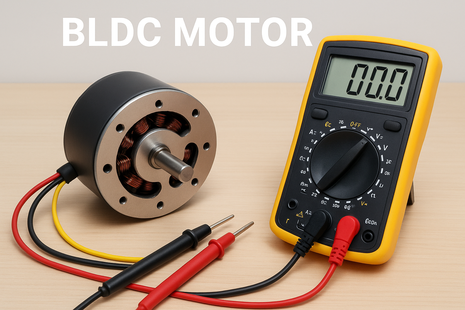
How to Test a BLDC Motor with a Multimeter?
Brushless DC (BLDC) motors have become the backbone of modern motion control applications—from electric vehicles and drones to industrial automation and robotics. Unlike traditional brushed motors, BLDC motors use electronic commutation instead of mechanical brushes, offering higher efficiency, longer lifespan, and smoother performance. However, just like any other motor type, BLDC motors can experience performance issues over time due to component wear, wiring faults, or insulation failures.
For engineers, maintenance teams, or even DIY enthusiasts, one of the most practical tools for diagnosing these issues is the multimeter. Testing a BLDC motor with a multimeter not only helps you identify electrical faults but also prevents potential system failures before they occur. In this blog, we’ll take a detailed look at how to test a BLDC motor using a multimeter, including what each test reveals, how to interpret your readings, and what to do if something seems off.
At United Motion Inc., we’ve spent years manufacturing and optimizing high-performance motion solutions—including precision-engineered 36mm BLDC motors—so we understand how essential accurate testing is for long-term reliability.
Understanding the Multimeter: Your Essential Diagnostic Tool
A multimeter is a versatile electronic measuring instrument used to check voltage, current, and resistance. For BLDC motor testing, a digital multimeter (DMM) is preferred for accuracy and clarity.
Here’s what the main settings mean:
- DC Voltage (VDC): Measures voltage in direct current circuits.
- AC Voltage (VAC): Measures alternating current voltage.
- Resistance (Ω): Measures the opposition to electrical current in ohms.
- Continuity Test: Checks if a circuit is complete.
- Diode Mode: Used for checking semiconductor components like Hall sensors.
For BLDC motors, the two most used functions are resistance and continuity, as they help detect open circuits or shorted windings.
Why Testing a BLDC Motor Matters?
Testing your BLDC motor periodically helps ensure optimal performance and reliability. Faults can occur in various parts of the motor—windings, bearings, or sensors—and if left undetected, can lead to more serious problems like overheating or complete failure.
Here are some common reasons to test your BLDC motor:
- Motor not starting or vibrating abnormally.
- Unusual noise during operation.
- Overheating even under normal load.
- Reduced speed or torque output.
- Irregular current draw or imbalance between phases.
Using a multimeter, you can easily detect the root causes behind these symptoms—often before they escalate into costly downtime.
Common Industry Pain Points When Testing BLDC Motors
Many professionals struggle with BLDC motor testing because the results are not always intuitive. One common pain point is inconsistent resistance readings, which often leads to confusion about whether the motor is defective or simply designed with low resistance.
Another issue is misdiagnosing controller problems as motor faults. Since BLDC motors require a driver, users may assume the motor is faulty when the real issue lies in the electronics. A proper multimeter test helps isolate the motor itself from the system.
Buyers and quality inspectors also face challenges when receiving motors from new suppliers. Without proper testing knowledge, it is difficult to verify product quality during incoming inspection. A simple multimeter test can provide confidence before integration or shipment.
Tools You Need to Test a BLDC Motor
To test a BLDC motor correctly, you do not need expensive equipment. A standard digital multimeter with resistance, continuity, and voltage measurement functions is sufficient for most checks. Ensure the multimeter is calibrated and has a low-resistance measurement range.
You may also need basic tools such as insulated probes, a wiring diagram if available, and a clean workspace. If the motor includes Hall sensors, access to the sensor connector pinout will help you perform accurate checks.
Using proper tools not only improves accuracy but also reduces the risk of damaging sensitive components during testing.
Safety Precautions Before Testing
Safety should always come first when working with electric motors. Make sure the BLDC motor is completely disconnected from the power supply and controller before testing. Residual voltage from capacitors in the driver can cause inaccurate readings or injury.
Avoid rotating the motor shaft aggressively during testing, as some BLDC motors can generate voltage when spun. Always handle probes carefully to prevent short circuits between phases.
Following these precautions ensures both personal safety and reliable test results.
Step-by-Step: How to Test a BLDC Motor with a Multimeter
Testing a BLDC motor involves checking several key aspects: winding resistance, continuity, short circuits, and Hall sensor functionality.
Let’s walk through each step in detail.
Step 1: Identify the Motor Terminals
Most BLDC motors have three main terminals for the windings, typically labeled U, V, and W (or sometimes A, B, and C). These represent the three motor phases. If your motor includes Hall sensors, you’ll also find additional smaller wires—usually 5 in total (Vcc, GND, and three signal wires).
Refer to the datasheet or color code from the manufacturer to confirm which wire corresponds to which terminal.
Step 2: Check Winding Continuity
- Set your multimeter to the continuity mode. Then:
- Touch the two probes to two of the phase terminals (U-V, V-W, and W-U).
- The multimeter should beep or show a low resistance reading (typically between 0.2Ω and 2Ω depending on the motor’s size and rating).
- Repeat for all three combinations.
- If one pair shows no continuity (OL or infinite), that phase winding is likely open-circuited.
Step 3: Measure Phase Resistance
- Switch the multimeter to the ohm (Ω) setting to measure phase-to-phase resistance precisely.
- Measure U-V, V-W, and W-U.
- The readings should be approximately equal. Small deviations (±10%) are acceptable.
- If one reading is significantly higher or lower, it indicates a shorted or partially damaged winding.
Example Chart: Typical BLDC Phase Resistance Readings
| Test Points | Ideal Reading (Ω) | Possible Issue |
|---|---|---|
| U – V | 0.8 Ω | Normal |
| V – W | 0.8 Ω | Normal |
| W – U | 0.8 Ω | Normal |
| U – V | Infinite (OL) | Open Winding |
| V – W | 0.1 Ω | Shorted Winding |
This simple comparison is often enough to identify internal faults without opening the motor housing.
Step 4: Check for Short Circuits to the Body (Ground Test)
- Now, check if the windings are shorted to the motor casing.
- Set the multimeter to continuity or resistance mode.
- Place one probe on the motor casing (metal body) and the other on each phase terminal (U, V, W).
- There should be no continuity—the multimeter should display OL (open loop).
- If continuity exists, there’s an internal insulation failure, and the motor needs repair or replacement.
Step 5: Test the Hall Sensors
Hall sensors are crucial for rotor position detection. Faulty sensors can cause the motor to misfire or fail to start.
To test:
- Connect the black probe of the multimeter to GND.
- Connect the red probe to one of the Hall signal wires.
- Power the Hall sensor circuit with a +5V supply (do not exceed recommended voltage).
- Slowly rotate the motor shaft by hand.
- The multimeter should alternate between 0V and 5V as the rotor moves.
- Repeat for all three Hall signal wires. If one signal doesn’t toggle, that Hall sensor is defective.
Step 6: Inspect Connector and Cable Integrity
Sometimes the problem isn’t inside the motor but within the connectors or cables. Check each terminal for looseness, corrosion, or frayed insulation. Resistance that fluctuates during movement often indicates a broken conductor inside the cable.
Interpreting the Results
Once you’ve taken all the measurements, interpret them against the motor’s specifications.
- Equal resistance on all phases: Motor windings are healthy.
- One open phase: Broken coil or internal wire disconnection.
- One low resistance phase: Possible short circuit between turns.
- Continuity to motor body: Insulation breakdown.
- Irregular Hall sensor signals: Faulty Hall element or misalignment.
These results will guide your next step—whether it’s rewinding, sensor replacement, or controller recalibration.
Common Problems Found During Testing
| Symptom | Possible Cause | Solution |
|---|---|---|
| Motor vibrates but doesn’t start | One phase open | Check winding continuity |
| Motor overheats | Shorted winding | Replace or rewind stator |
| Motor jerks at low speed | Faulty Hall sensor | Replace sensor |
| Uneven current draw | Phase imbalance | Verify resistance and controller output |
| Noise and reduced torque | Bearing or mechanical misalignment | Inspect rotor and bearings |
Understanding these common failure modes allows technicians to focus repairs effectively.
Preventive Maintenance Tips for BLDC Motors
Regular testing is part of preventive maintenance. To extend the lifespan of your BLDC motor:
- Keep it clean and dry to avoid corrosion.
- Ensure proper ventilation to prevent overheating.
- Use a current-limited power supply during bench testing.
- Avoid sudden load changes or voltage spikes.
- Recheck phase balance every few months for mission-critical systems.
United Motion Inc. recommends testing motor resistance and insulation at least once every six months for continuous-duty applications.
When to Replace the Motor
Even the best BLDC motors eventually wear out. Consider replacing your motor if:
- The winding resistance shows large deviations.
- There’s internal shorting to the housing.
- Bearings are noisy despite lubrication.
- The motor requires frequent sensor replacements.
United Motion Inc. offers a wide range of 36mm BLDC motor models that meet these replacement needs, featuring low noise, high torque density, and long service life for demanding applications.
How Buyers Can Use This Testing Method?
For procurement teams and engineers sourcing motors globally, these tests are extremely valuable.
When working with a BLDC motor manufacturer like United Motion Inc., you can use these checks to validate product consistency, especially in bulk orders.
Incoming quality inspection (IQC) can include:
• Phase resistance comparison
• Insulation testing
• Back EMF verification
This ensures that all motors meet your application requirements before deployment.
When a Multimeter Is Not Enough?
While multimeters are useful, they have limitations.
They cannot detect:
• Dynamic performance issues under load
• Controller-related faults
• Magnetic field irregularities
For deeper analysis, tools like oscilloscopes, motor analyzers, and thermal imaging cameras are recommended.
However, for 80% of real-world troubleshooting scenarios, a multimeter is more than sufficient.
Troubleshooting Flowchart
Below is a simplified troubleshooting flow to visualize the testing process.
Start
↓
Check Continuity Between Phases
↓
[OK] → Check Phase Resistance → [Equal] → Test Hall Sensors → [OK] → Motor Healthy
↓
[Not OK] → Open/Short Winding → Repair or Replace Motor
↓
Check Ground Insulation
↓
[Fail] → Replace Motor
↓
End
Frequently Asked Questions (FAQ)
Q1: Can I test a BLDC motor without a controller?
Yes. Using a multimeter, you can test for continuity, resistance, and insulation without needing the controller connected.
Q2: What if my BLDC motor has more than three wires?
Some BLDC motors include Hall sensors or temperature sensors. Always consult the wiring diagram before testing.
Q3: Why do my phase resistances differ slightly?
Small differences are normal. However, large variations indicate winding imbalance or damage.
Q4: Can a multimeter detect winding shorts accurately?
It can detect major faults. For microscopic turn-to-turn shorts, advanced tools like LCR meters or surge testers are needed.
Q5: How often should I test my BLDC motor?
Every 6 to 12 months, or whenever abnormal vibration, noise, or heat is noticed.
References
Hughes, A. & Drury, B. (2019). Electric Motors and Drives: Fundamentals, Types and Applications. Elsevier.
Chapman, S. J. (2012). Electric Machinery Fundamentals. McGraw-Hill.
United Motion Inc. Internal Product Documentation, 2025.
P. C. Sen (2013). Principles of Electric Machines and Power Electronics. Wiley.
IEEE Industry Applications Society. Testing and Diagnostics of BLDC Machines, Journal of Applied Mechanics (2021).