
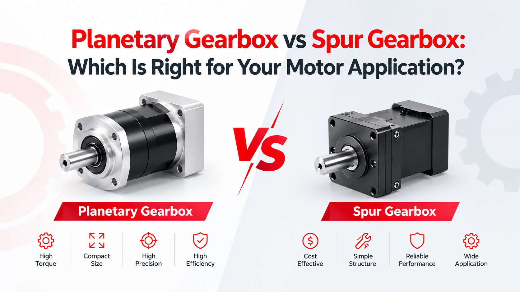
Quick Answer: Planetary Gearbox vs Spur Gearbox
The main difference between a planetary gearbox and a spur gearbox is how the gears transmit torque. A planetary gearbox uses a sun gear, multiple planet gears, and a ring gear, allowing torque to be distributed through several gear meshes. A spur gearbox normally uses one or more pairs of externally meshing spur gears to obtain the required reduction ratio.
In practical motor applications, planetary gearboxes generally provide higher power density, better torque capacity relative to size, and more compact packaging, while spur gearboxes are usually simpler, easier to manufacture, and more economical for moderate-load applications.
The correct selection should therefore be based on output torque, reduction ratio, speed, duty cycle, radial and axial loads, allowable backlash, noise, installation space, efficiency, and cost rather than gearbox type alone.
Research from The Ohio State University Gear and Power Transmission Research Laboratory has specifically investigated planetary load sharing, efficiency, transmission error, and gear dynamics, while NASA research has examined power losses and efficiency in both planetary and spur gear systems.
What Is a Planetary Gearbox?
A planetary gearbox typically consists of three primary elements: a sun gear, planet gears, and ring gear, with the planet gears mounted on a carrier.
Because multiple planet gears can share the transmitted load, the gearbox can achieve relatively high torque capacity within a compact diameter. The arrangement also allows different elements to serve as the input, output, or fixed member, providing substantial flexibility in gear-ratio configuration.
The Ohio State University, in research presented by its Gear and Power Transmission Research Laboratory, identifies higher power density, lower radial support loads, kinematic flexibility, and load-sharing behavior among important characteristics of planetary transmissions. The laboratory’s research program includes planetary load distribution, efficiency, and dynamic behavior.
For compact BLDC gear motor systems, this packaging advantage can be important because a BLDC motor may operate at several thousand RPM while the application requires substantially lower output speed and higher torque.
For example, UNITED MOTION INC. offers BLDC motors from 28 mm to 110 mm frame diameters, with gearbox integration, encoder integration, Hall sensors, and driver integration available for applications including robotics, industrial automation, solar tracking, pumps, lawn equipment, and electric mobility.
What Is a Spur Gearbox?
A spur gearbox uses straight-cut cylindrical gears whose teeth are parallel to the rotational axis.
Its relatively simple construction makes spur gears attractive for applications where cost, straightforward manufacturing, and serviceability are important. However, as reduction ratio and output torque requirements increase, multiple gear stages may be required, which can increase gearbox length, the number of components, and cumulative transmission losses.
NASA Technical Publication NASA-TP-1622, published in 1980 by NASA Lewis Research Center, analyzed spur-gear-system power losses and identified gear sliding, rolling traction, windage, and bearing losses as contributors to overall gearbox loss.
This means that quoting a single “gear efficiency” value without specifying operating speed, load, lubrication, gear geometry, and bearing conditions can be misleading.
Planetary Gearbox vs Spur Gearbox: Key Differences
| Parameter | Planetary Gearbox | Spur Gearbox |
| Torque density | Generally high | Moderate |
| Package size | Compact for high torque | Usually larger for equivalent high torque |
| Load sharing | Multiple planets can share load | Primarily through individual gear meshes |
| Reduction ratio | Suitable for multi-stage compact reduction | Often requires additional stages for high ratios |
| Backlash | Can be designed for low backlash | Depends strongly on gear and assembly tolerances |
| Efficiency | High, but multiple meshes/bearings create losses | High for well-designed stages |
| Manufacturing complexity | Higher | Lower |
| Cost | Generally higher | Generally lower |
| Serviceability | More complex | Relatively simple |
| Typical applications | Robotics, servo systems, compact drives | General machinery, conveyors, actuators |
These are engineering tendencies rather than absolute rules. Gear geometry, materials, lubrication, bearing selection, manufacturing tolerances, and operating conditions can substantially change actual performance. NASA and Ohio State research both demonstrate that gearbox losses and load distribution must be evaluated as system-level characteristics.
Planetary vs Spur Gearbox Efficiency
It is incorrect to assume that a planetary gearbox is automatically more efficient than a spur gearbox.
A spur gear pair can have very low mesh losses when correctly designed and lubricated. NASA’s 1980 spur-gear efficiency research showed that gear-system losses are influenced by sliding, rolling traction, windage, and bearing losses.
Planetary gearboxes introduce additional gear meshes and planet bearings, so they can have additional load-dependent and load-independent losses. Dr. David Talbot’s 2012 Ohio State University doctoral research experimentally investigated planetary gear-set power losses and identified gear mesh, planet-bearing, lubrication-related, and drag losses as important contributors.
Therefore, when comparing two gearboxes, engineers should request measured efficiency at the actual operating speed, torque, and reduction ratio, rather than relying only on a generic efficiency percentage.
How to Select the Right Gearbox for a BLDC Motor?
Step 1: Determine Required Output Torque
Calculate both continuous and peak torque.
A simplified relationship is:
T_out ≈ T_motor × i × η
where:
- T_out = gearbox output torque
- T_motor = motor torque
- i = reduction ratio
- η = gearbox efficiency
For example, a 0.8 N·m motor with a 10:1 gearbox operating at 90% efficiency would theoretically provide approximately:
0.8 × 10 × 0.90 = 7.2 N·m
at the gearbox output.
Step 2: Determine Output Speed
The approximate relationship is:
n_out ≈ n_motor / i
If a BLDC motor operates at 3,000 RPM and a 10:1 reduction is used, the nominal gearbox output speed is approximately 300 RPM, before considering load-dependent slip or control effects.
UNITED MOTION INC.’s BLDC portfolio includes examples operating around 3,000 RPM, with available torque and power varying significantly by frame size. For example, its 60 mm series includes configurations rated at 188 W and 377 W, while its 110 mm series reaches 1,100 W and 1,413 W in listed configurations.
Step 3: Check Radial and Axial Loads
Do not select a gearbox only from its output torque.
If the gearbox directly drives a pulley, wheel, belt, lead screw, or external mechanism, calculate the radial and axial forces acting on the output shaft and compare them with the manufacturer’s allowable loads.
Step 4: Evaluate Backlash and Position Accuracy
For conveyors and simple actuators, moderate backlash may be acceptable.
For robotics, camera tracking, positioning systems, or servo applications, backlash and transmission error can become much more important.
Ohio State research has specifically examined transmission error, manufacturing errors, and planet-to-planet load sharing in planetary gear sets.
Step 5: Check Noise, Duty Cycle, and Thermal Conditions
Gearbox noise depends on tooth geometry, pitch, speed, backlash, manufacturing accuracy, lubrication, bearings, housing stiffness, and assembly.
For a BLDC motor, the gearbox should also be evaluated together with the motor’s electromagnetic noise and control strategy. A mechanically quiet gearbox does not automatically produce a quiet motor assembly.
Common Gearbox Selection Problems
| Problem | Possible Cause | Engineering Check |
| Output torque is insufficient | Motor or ratio undersized | Recalculate continuous and peak torque |
| Gearbox overheats | Excessive load or poor lubrication | Check efficiency, duty cycle, lubrication |
| Excessive backlash | Gear clearance or wear | Check backlash specification |
| High operating noise | Gear mesh or assembly error | Check alignment, tooth condition, housing |
| Shaft failure | Excessive radial/axial load | Calculate external shaft loads |
| Motor overheats | Gearbox load too high | Check motor current and operating point |
| Short gearbox life | Overload or contamination | Review duty cycle and environment |
A common mistake is sizing the gearbox only from nominal motor torque. Acceleration torque, starting torque, shock loads, duty cycle, and external shaft loads can be more demanding than steady-state operation.
When Should You Choose a Planetary Gearbox?
A planetary gearbox is generally worth considering when the design requires:
- High torque in a compact package
- High power density
- Multiple reduction stages in limited space
- Low radial support loads
- Precise motion transmission
- Integration with BLDC or servo motors
- Robotics or automation applications
This makes planetary gearing particularly relevant when a compact BLDC motor and gearbox must deliver significantly higher output torque without proportionally increasing the motor and gearbox envelope.
When Should You Choose a Spur Gearbox?
A spur gearbox can be appropriate when:
- The required torque is moderate
- Packaging space is less restrictive
- Cost is a major design constraint
- The mechanism is relatively simple
- Extremely low backlash is not required
- Easy manufacturing and maintenance are important
For general-purpose actuators, conveyors, pumps, and other moderate-load systems, a properly designed spur gearbox can provide an effective and efficient transmission solution.
Final Engineering Consideration
The Planetary Gearbox vs Spur Gearbox decision should not be reduced to “which gearbox is better.” The engineering question is which transmission architecture can meet the required torque, speed, efficiency, backlash, noise, load capacity, lifetime, envelope, and cost at the application’s actual operating point.
For a BLDC motor system, gearbox selection should also be performed together with motor and controller selection. UNITED MOTION INC. supports BLDC motor configurations from 28–110 mm, with options for gearbox, encoder, Hall sensor, and driver integration, allowing the motor, feedback, transmission, and control system to be evaluated as one motion-control assembly.
Frequently Asked Questions
1. What is the main difference between a planetary gearbox and a spur gearbox?
A planetary gearbox distributes torque through multiple planet gears around a sun gear, while a spur gearbox normally transmits torque through pairs of externally meshing straight-tooth gears.
2. Is a planetary gearbox more efficient than a spur gearbox?
Not necessarily. Both can achieve high efficiency, but actual efficiency depends on gear geometry, reduction ratio, speed, load, bearings, lubrication, and the number of gear meshes.
3. Which gearbox provides higher torque density?
Planetary gearboxes generally provide higher torque density because multiple planets can participate in transmitting the load within a compact package.
4. Which gearbox is cheaper?
Spur gearboxes are generally less complex and can be less expensive to manufacture, although the actual cost depends on materials, precision, ratio, bearings, housing, and production volume.
5. Can a planetary gearbox be used with a BLDC motor?
Yes. Planetary gearboxes are commonly integrated with BLDC motors when the application requires lower output speed and higher output torque within a compact package.
6. How do I calculate gearbox output torque?
A preliminary calculation is T_out ≈ T_motor × reduction ratio × gearbox efficiency. Final sizing should also consider peak loads, acceleration, duty cycle, thermal limits, and allowable gearbox torque.
7. Does a higher gear ratio always produce a better motor system?
No. Increasing the reduction ratio increases theoretical output torque and decreases output speed, but it can also increase gearbox size, losses, inertia, backlash, and mechanical complexity.
8. What should I provide to a gearbox manufacturer?
Provide required output torque, output speed, motor specifications, reduction ratio, duty cycle, peak load, radial and axial loads, mounting dimensions, shaft requirements, operating temperature, noise requirements, backlash requirements, and expected service life.