
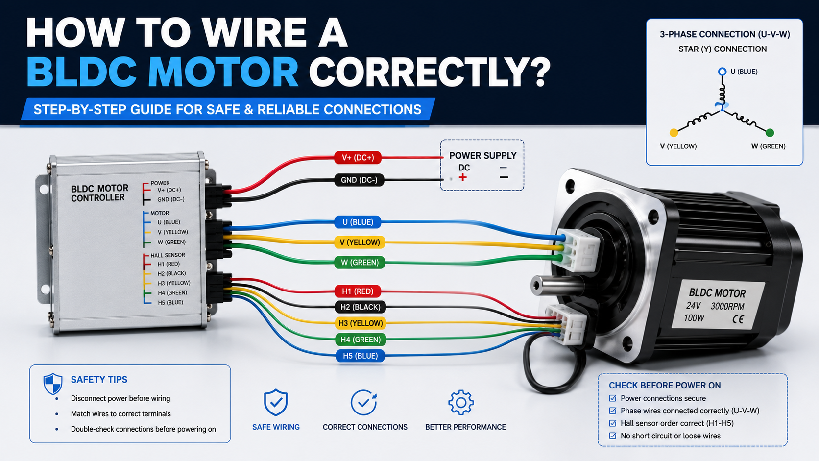
Correctly wiring BLDC Motors requires matching the motor phases (U/V/W) to the controller outputs, connecting the Hall sensor signals correctly (if equipped), supplying the controller with the proper DC voltage, and configuring controller parameters according to the motor specifications. Incorrect wiring can cause reverse rotation, excessive current, poor efficiency, vibration, overheating, or permanent damage to both the motor and the controller.
According to the U.S. Department of Energy (DOE) and NEMA MG 1 Motor Standards, proper motor wiring and commissioning are essential for achieving rated efficiency, reducing maintenance costs, and ensuring operational safety.
Why Correct Wiring Matters for BLDC Motors?
Unlike brushed DC motors, BLDC Motors rely entirely on electronic commutation. The controller determines which winding should be energized based on rotor position feedback from Hall sensors or sensorless back-EMF detection.
If any phase or sensor wire is connected incorrectly, the controller cannot accurately determine rotor position, resulting in unstable operation.
Typical problems caused by incorrect wiring include:
- Reverse rotation
- Severe vibration
- High startup current
- Motor overheating
- Reduced torque
- Low efficiency
- Controller fault alarms
- Permanent MOSFET damage
Research published by the IEEE Industry Applications Society (IEEE IAS, 2022) indicates that improper phase sequencing and Hall sensor mismatches remain among the leading causes of BLDC commissioning failures in industrial automation systems.
Understanding the Basic Wiring of BLDC Motors
Before connecting any wires, engineers should understand the electrical architecture of a BLDC system.
Main Components
A typical BLDC drive system consists of:
- BLDC Motor
- Motor Controller (ESC or Servo Driver)
- DC Power Supply
- Hall Sensor Cable (optional)
- Encoder (optional)
- Communication Interface (CAN, RS485, EtherCAT, etc.)
The controller converts DC voltage into a three-phase PWM waveform to drive the stator windings.
Standard BLDC Motor Wiring Diagram
Most industrial BLDC Motors contain two independent wiring groups.
Power Phase Wires
Usually three thick wires:
- U
- V
- W
These wires carry the motor current.
Typical specifications:
| Parameter | Typical Value |
| Wire Gauge | AWG14–AWG22 |
| Voltage | 12V–310V DC |
| Current | 2A–80A |
| Insulation | 300–600V |
Hall Sensor Cable
Typically five or six wires:
| Signal | Typical Color |
| +5V | Red |
| GND | Black |
| Hall A | Yellow |
| Hall B | Green |
| Hall C | Blue |
| Temperature (optional) | White |
Hall sensors detect rotor position every 60 electrical degrees.
According to Texas Instruments BLDC Motor Control Fundamentals (2023), Hall sensors simplify startup and provide accurate low-speed commutation.
Step-by-Step Guide to Wire a BLDC Motor Correctly
Step 1. Verify Motor Specifications
Before wiring, confirm the motor nameplate.
Check:
- Rated voltage
- Rated current
- Number of poles
- Hall sensor voltage
- Rated speed
- Maximum speed
- Power rating
Example:
- 24V
- 400W
- 3000 RPM
- Hall sensors: 5V
Never assume every BLDC Motor uses identical wiring.
Step 2. Disconnect Power
Always disconnect:
- Main DC power
- Battery
- Capacitors
- Emergency backup supply
Industrial controllers may retain high voltage even after shutdown.
The Occupational Safety and Health Administration (OSHA) recommends verifying zero energy before servicing electrical equipment.
Source: OSHA Lockout/Tagout Standard (29 CFR 1910.147), U.S. Department of Labor.
Step 3. Connect the Three Motor Phases
Match controller outputs:
Controller → Motor
U → U
V → V
W → W
Do not randomly interchange wires during initial installation.
If rotation is reversed, swap any two phase wires only after confirming Hall sensor compatibility, or change the rotation direction through the controller software if supported.
Step 4. Connect Hall Sensor Wires
Typical wiring:
| Controller | Motor |
| +5V | Red |
| GND | Black |
| HA | Yellow |
| HB | Green |
| HC | Blue |
Many controllers label these as:
- Hall A
- Hall B
- Hall C
Incorrect Hall wiring causes:
- Rough startup
- Noise
- High current
- Controller faults
Step 5. Verify Supply Voltage
Measure the power supply using a multimeter.
Typical industrial ranges:
| Motor Rating | Supply Voltage |
| Small BLDC | 12–24V |
| Medium BLDC | 24–48V |
| Industrial Servo BLDC | 48–310V |
Undervoltage reduces torque.
Overvoltage may permanently damage the controller.
Step 6. Secure All Connections
Loose terminals generate resistance.
Resistance causes:
- Heat
- Voltage drop
- Connector discoloration
- Fire risk
Use:
- Crimp terminals
- Lock washers
- Proper torque
- Shielded cables
Step 7. Perform Initial Startup
Start at low speed.
Monitor:
- Current
- Speed
- Noise
- Temperature
- Vibration
Gradually increase speed while monitoring current consumption.
According to IEC 60034 rotating machine standards, commissioning should begin under no-load conditions before applying the rated load.
Sensored vs Sensorless BLDC Wiring
| Feature | Sensored BLDC | Sensorless BLDC |
| Phase Wires | 3 | 3 |
| Hall Cable | Required | Not Required |
| Low-Speed Torque | Excellent | Moderate |
| Startup Performance | Excellent | Fair |
| Wiring Complexity | Higher | Lower |
| Typical Applications | AGVs, Medical Equipment, Robotics | Fans, Pumps, Power Tools |
Sensorless systems simplify installation but generally provide less reliable low-speed performance because rotor position must be estimated from back electromotive force (back-EMF), which becomes difficult at zero or very low speed.
Common Wiring Mistakes
Mixing Hall Sensor Signals
One incorrect Hall signal can prevent proper commutation.
Symptoms:
- Jerking
- Noise
- Controller alarms
- Reversing Power Polarity
Reverse polarity can instantly destroy:
- MOSFET bridge
- Capacitors
- Controller PCB
Many industrial drives include reverse-polarity protection, but it should never be relied upon as the primary safeguard.
Using Undersized Cables
Small cables create:
- Voltage drop
- Heating
- Reduced torque
Recommended current density:
4–6 A/mm² for continuous industrial applications.
Ignoring Shield Grounding
Long motor cables may introduce:
- Electromagnetic interference (EMI)
- Encoder errors
- Communication failures
Use shielded cables with proper grounding practices.
Troubleshooting Wiring Problems
| Symptom | Possible Cause | Solution |
| Motor does not rotate | No power | Check DC supply |
| Motor vibrates | Incorrect phase sequence | Verify U/V/W wiring |
| Runs backward | Phase sequence reversed | Swap two phases or adjust controller settings |
| High current | Hall mismatch | Check Hall wiring |
| Overheating | Loose terminals | Tighten connectors |
| Controller alarm | Incorrect Hall voltage | Measure Hall supply |
| Noise during startup | Poor commutation | Verify Hall sequence |
| Low torque | Undervoltage | Check power supply |
Engineering Best Practices
Professional engineers typically follow these recommendations:
- Label every cable before installation.
- Verify wiring continuity using a digital multimeter before applying power.
- Use shielded motor cables for cable lengths exceeding approximately 3 meters in electrically noisy industrial environments.
- Separate motor power cables from signal and communication cables to reduce electromagnetic interference.
- Follow the controller manufacturer’s recommended wiring diagram rather than relying solely on wire colors, as color conventions vary by supplier.
- Record baseline current, speed, and temperature values during commissioning for future maintenance comparisons.
- Configure controller protection parameters such as overcurrent, overvoltage, and thermal limits before full-load testing.
- Ensure all connectors meet the required ingress protection (IP) rating for the operating environment, especially in outdoor or high-humidity applications.
Typical Wiring Specifications
| Parameter | Typical Range |
| Voltage | 12–310 VDC |
| Power | 10 W–5 kW+ |
| Current | 1–100 A |
| Hall Voltage | 5 V |
| Number of Phases | 3 |
| PWM Frequency | 8–25 kHz |
| Efficiency | 85–96% |
| Protection Class | IP20–IP67 |
These values vary depending on motor size, application, cooling method, and controller design.
Why Choose UNITED MOTION INC. for BLDC Motors?
At UNITED MOTION INC., we provide engineered BLDC motor solutions for OEMs, automation equipment manufacturers, and industrial system integrators. Our portfolio includes compact and high-power BLDC motors with customizable voltage, torque, speed, shaft configurations, integrated gearboxes, Hall sensors, encoders, and dedicated motor controllers.
Our engineering team supports customers throughout the entire development cycle—from motor selection and wiring guidance to controller matching, rapid prototyping, testing, and volume production—helping reduce integration risks and accelerate time to market for demanding motion-control applications.
Conclusion
Correct wiring is one of the most critical steps in ensuring the reliable performance of BLDC Motors. By understanding phase connections, Hall sensor wiring, controller configuration, supply voltage requirements, and proper commissioning procedures, engineers can significantly reduce startup failures, improve efficiency, and extend the service life of both the motor and the drive system.
Whether the application involves industrial automation, AGVs, medical equipment, electric lawn equipment, or robotics, following standardized wiring practices and validating every connection before energizing the system will lead to safer operation, higher reliability, and lower maintenance costs.
Frequently Asked Questions
1. Can a BLDC motor run if two phase wires are swapped?
Yes. Swapping any two phase wires typically reverses the rotation direction, provided the Hall sensor sequence remains compatible with the controller. If Hall signals no longer align, the motor may vibrate, draw excessive current, or fail to start properly.
2. What voltage do Hall sensors usually require?
Most industrial BLDC Motors use 5 VDC Hall sensors, although some automotive and specialized systems may use 3.3 V or 12 V. Always verify the motor datasheet before applying power.
3. How can I tell if my BLDC motor wiring is correct?
A correctly wired BLDC motor should start smoothly, rotate in the intended direction, operate quietly with stable current draw, and maintain normal operating temperature without controller fault alarms.
4. Can I operate a BLDC motor without Hall sensors?
Yes. Many controllers support sensorless operation, using back-EMF estimation for rotor position. However, startup torque and low-speed control are generally less precise than with sensored systems.
5. Why does my BLDC motor become hot immediately after wiring?
Immediate overheating often indicates incorrect phase or Hall sensor connections, an overvoltage supply, excessive mechanical load, or incorrect controller parameter settings. Disconnect power immediately and inspect the wiring before further operation.
Related blog: What are the key benefits of using BLDC motors?