
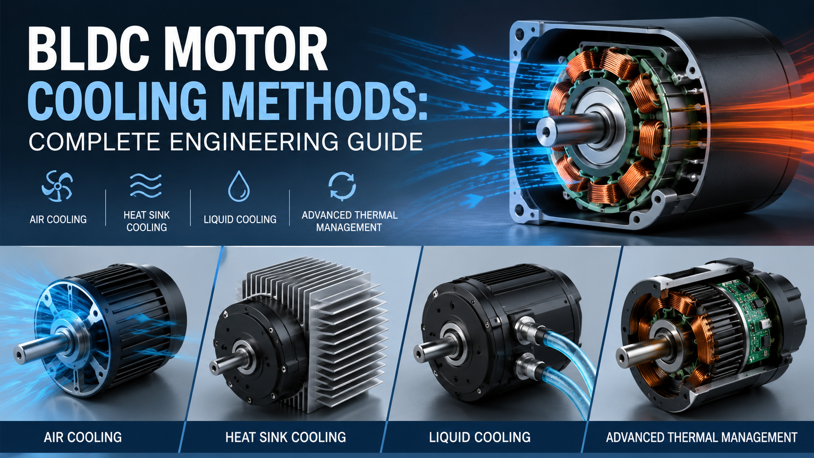
BLDC motors generate heat from copper losses, iron losses, bearing friction, and inverter switching losses. Effective cooling methods—including natural air cooling, forced-air cooling, liquid cooling, heat sinks, cooling fins, thermal interface materials, and intelligent thermal monitoring—help maintain winding temperatures below insulation limits, improve efficiency by reducing copper resistance, extend bearing life, and increase continuous torque capability.
For most industrial BLDC motors:
| Cooling Method | Typical Power Range | Advantages | Typical Applications |
| Natural Air Cooling | 10–300 W | Simple, low cost | Fans, pumps, small automation |
| Forced Air Cooling | 200 W–5 kW | Higher continuous torque | Industrial automation |
| Heat Sink Cooling | 50 W–2 kW | Compact solution | Servo systems |
| Liquid Cooling | 2 kW–200 kW+ | Highest cooling efficiency | EVs, robotics, aerospace |
| Oil Cooling | High-power systems | Excellent heat transfer | Traction motors |
Engineering takeaway: Selecting the proper cooling method should be based on continuous power, ambient temperature, duty cycle, enclosure design, and allowable winding temperature rather than motor power alone.
Why BLDC Motors Need Cooling?
Although BLDC Motors are typically 10–20% more efficient than comparable brushed DC motors, they are not heat-free. Every watt of electrical loss becomes thermal energy that must be removed.
The major heat sources include:
- Copper (I²R) losses in stator windings
- Iron (core) losses caused by alternating magnetic fields
- Eddy current losses
- Hysteresis losses
- Bearing friction
- Windage losses
- MOSFET or IGBT switching losses inside the motor controller
According to IEEE Industry Applications Society (2022) and the U.S. Department of Energy, copper loss is generally the largest heat source under heavy load, while iron loss becomes increasingly significant at higher rotational speeds.
How Heat Affects BLDC Motor Performance?
Proper thermal management directly affects nearly every performance parameter of a BLDC motor.
Reduced Efficiency
Copper resistance increases approximately 0.39% per °C.
If winding temperature rises from 25°C to 125°C:
- Resistance increases nearly 40%
- Copper losses increase significantly
- Motor efficiency decreases
Reduced Magnet Strength
Permanent magnets lose magnetic flux as temperature rises.
Typical maximum operating temperatures:
| Magnet Grade | Maximum Temperature |
| N35 NdFeB | 80°C |
| N42SH | 150°C |
| SmCo | 250–350°C |
Operating above these temperatures may cause irreversible demagnetization.
Shorter Bearing Life
Bearing grease oxidizes rapidly at elevated temperatures.
A common engineering rule states:
Every 15°C increase above rated bearing temperature approximately halves lubricant life.
Insulation Aging
Motor insulation follows the Arrhenius aging model.
For many insulation systems:
Every 10°C increase above the insulation class approximately reduces insulation life by 50%.
Understanding Heat Flow Inside a BLDC Motor
Heat generated inside the stator must travel through multiple thermal paths before reaching the surrounding air.
The typical heat transfer path is:
Copper winding
↓
Stator core
↓
Motor housing
↓
Cooling surface
↓
Ambient air or coolant
Each interface introduces thermal resistance. Poor contact between components can significantly reduce cooling efficiency.
Engineers therefore focus on minimizing thermal resistance using:
- Aluminum housings
- Thermal epoxy
- Potting compounds
- Heat-conductive interface materials
- Larger external surface areas
Common BLDC Motor Cooling Methods
1. Natural Air Cooling
Natural convection relies on surrounding air without additional fans.
- Advantages
- Lowest cost
- No maintenance
- No additional power consumption
- High reliability
- Limitations
- Limited heat dissipation
- Sensitive to ambient temperatureLower continuous torque
Typical applications include:
- Medical equipment
- Smart home products
- Small conveyors
- Laboratory equipment
Typical thermal resistance:
3–10°C/W
2. Forced-Air Cooling
Forced-air cooling uses fans or blowers to increase airflow over the motor housing.
Compared with natural convection:
- 2–5× higher heat transfer coefficient
- Increased continuous power
- Lower winding temperatures
Typical airflow:
10–100 CFM depending on motor size.
Common applications:
- CNC machines
- Packaging equipment
- Textile machinery
- Automated production lines
3. Cooling Fins
Cooling fins increase the external surface area available for heat transfer.
The increased area allows more heat to dissipate without increasing motor size.
Good fin design considers:
- Fin spacing
- Fin thickness
- Airflow direction
- Surface roughness
Aluminum extruded housings are commonly used because of their excellent thermal conductivity (approximately 205 W/m·K).
4. Heat Sink Cooling
Heat sinks provide additional thermal mass and improve conduction away from the stator.
Heat sinks are especially useful when motors are mounted to metal machine frames.
Design considerations include:
- Contact flatness
- Thermal grease
- Mounting pressure
- Interface resistance
Poor mounting can reduce cooling performance by over 30%.
5. Liquid Cooling
Liquid cooling is the preferred solution for high-power-density BLDC motors.
Coolant channels circulate water or water-glycol mixtures around the motor housing.
Advantages include:
- Extremely high heat transfer coefficient
- Compact motor size
- Stable operating temperature
- Higher continuous torque
- Lower winding resistance
Typical coolant temperature:
20–60°C
Heat transfer coefficient:
500–10,000 W/m²·K
Common applications:
- Electric vehicles
- Industrial robots
- AGVs
- Aerospace systems
- High-speed spindles
According to SAE International, liquid cooling can increase continuous motor output by more than 50% compared with air-cooled designs under identical housing dimensions.
6. Oil Cooling
Oil cooling directly contacts rotating components.
Advantages:
- Excellent heat transfer
- Lubrication
- Reduced bearing temperature
- Rotor cooling
Typically used in:
- EV traction motors
- Heavy machinery
- Aerospace
Comparison of BLDC Motor Cooling Methods
| Cooling Method | Cost | Cooling Capacity | Maintenance | Typical Efficiency Improvement |
| Natural Air | Low | Low | None | Baseline |
| Forced Air | Medium | Medium | Fan maintenance | 5–15% |
| Cooling Fins | Low | Medium | None | 5–10% |
| Heat Sink | Medium | Medium | None | 5–12% |
| Liquid Cooling | High | Excellent | Coolant system | 15–30% |
| Oil Cooling | High | Excellent | High | 20–35% |
Step-by-Step Guide to Choosing the Right Cooling Method
Step 1: Determine Continuous Power
Peak power does not determine cooling requirements.
Continuous RMS power is the primary design criterion.
Step 2: Evaluate Ambient Temperature
Industrial motors may operate in environments ranging from:
-20°C
25°C
40°C
60°C
Higher ambient temperatures reduce cooling effectiveness.
Step 3: Identify Duty Cycle
Examples include:
- Continuous operation (S1)
- Intermittent duty (S3)
- Repetitive duty (S6)
Continuous-duty motors require much better thermal management.
Step 4: Consider Enclosure Rating
IP65 and IP67 motors have lower natural heat dissipation because airflow is restricted.
Liquid cooling often becomes preferable.
Step 5: Verify Insulation Class
Common insulation classes:
| Class | Maximum Temperature |
| B | 130°C |
| F | 155°C |
| H | 180°C |
Motor design should maintain sufficient thermal margin below the insulation limit during continuous operation.
Common Cooling Design Mistakes
Many overheating issues originate from system-level design rather than the motor itself.
Common mistakes include:
- Selecting a motor based only on peak torque
- Blocking ventilation openings
- Installing motors inside sealed enclosures without airflow
- Ignoring controller-generated heat
- Using incorrect thermal grease
- Poor mounting contact
- Underestimating ambient temperature
- Operating continuously at stall torque
These issues often cause winding temperatures to exceed safe limits, reducing motor reliability and service life.
Troubleshooting BLDC Motor Overheating
| Problem | Possible Cause | Recommended Solution |
| Housing too hot | Insufficient airflow | Improve ventilation or add forced-air cooling |
| Winding overheating | Continuous overload | Select a larger motor or reduce load |
| Bearings overheating | Lubrication failure | Replace bearings and lubricant |
| Motor shuts down | Thermal protection activated | Verify duty cycle and cooling capacity |
| Reduced torque | Magnet temperature too high | Improve cooling or use higher-temperature magnets |
| Controller overheating | Poor inverter ventilation | Add heatsink or improve controller airflow |
Best Practices for Thermal Management
Experienced motor designers often combine multiple cooling strategies rather than relying on a single method.
Recommended practices include:
Select the appropriate cooling solution based on continuous thermal load instead of peak output.
Use high-conductivity aluminum housings with optimized fin geometry to increase heat dissipation.
Improve thermal interfaces between the stator and housing with quality thermal compounds or potting materials.
Integrate temperature sensors (PT100, NTC thermistors, or embedded thermal switches) for real-time monitoring.
Match magnet grade, insulation class, and bearing specifications to the expected operating temperature.
Simulate thermal performance during the design stage using finite element analysis (FEA) to identify hot spots before production.
Schedule regular maintenance for forced-air and liquid-cooled systems to prevent blocked airflow, coolant degradation, or pump failures.
Conclusion
Effective thermal management is essential for maximizing the efficiency, reliability, and service life of BLDC Motors. While natural air cooling is adequate for many low-power applications, higher continuous loads often require enhanced solutions such as forced-air cooling, optimized heat sinks, or liquid cooling systems. The optimal approach depends on the motor’s power density, duty cycle, enclosure rating, ambient environment, and allowable operating temperature. By designing with thermal performance in mind and avoiding common installation mistakes, engineers can significantly improve continuous torque capability, reduce maintenance costs, and extend equipment lifespan.
Frequently Asked Questions
Does a BLDC motor always need active cooling?
No. Small BLDC motors operating at low continuous loads often rely on natural convection. Active cooling becomes necessary when heat generation exceeds the motor housing’s ability to dissipate it.
Which cooling method offers the highest efficiency?
Liquid cooling provides the highest heat removal capability and is commonly used for high-power-density motors in electric vehicles, robotics, and industrial automation.
What temperature is considered too high for a BLDC motor?
It depends on the insulation class and magnet material. In general, winding temperatures should remain below the insulation rating (such as 155°C for Class F), while permanent magnets should stay below their specified maximum operating temperature to avoid irreversible demagnetization.
Can better cooling increase motor torque?
Yes. Lower operating temperatures reduce winding resistance, allowing the motor to sustain higher continuous current and therefore higher continuous torque without exceeding thermal limits.
How can I tell if my BLDC motor is overheating?
Common signs include excessive housing temperature, thermal shutdown, reduced torque, unusual bearing noise, insulation odor, or repeated activation of temperature protection.
Related blog: What is the Best Voltage for BLDC Motor?