
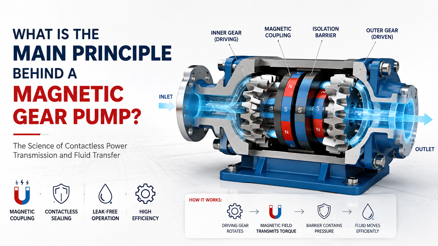
The main principle behind a Magnetic Gear Pump is the combination of positive-displacement gear pumping and non-contact magnetic torque transmission. Instead of using a conventional shaft seal to connect the motor to the pumping gears, permanent magnets transfer torque through a sealed containment barrier. As the gears rotate, they create expanding cavities at the inlet that draw fluid into the pump, carry the trapped fluid around the housing, and compress it toward the outlet. The magnetic coupling therefore performs the drive function, while the gear set performs the actual pumping function.
This architecture is particularly useful when leakage prevention, chemical compatibility, compact packaging, or contamination control is more important than achieving the absolute minimum cost.
What Is a Magnetic Gear Pump?
A magnetic gear pump is essentially a rotary positive-displacement pump equipped with a magnetic drive system. Its main components normally include a driving magnet assembly, driven magnet assembly, containment shell, gear set, pump housing, bearings or bushings, inlet, and outlet.
The motor rotates the external magnetic rotor, and the magnetic field transfers torque across the containment shell to the internal rotor connected to the pump gear. Because there is no mechanical shaft penetrating the pressure boundary, the conventional dynamic shaft seal can be eliminated.
A 2004 World Pumps engineering article by Steven E. Owen of Micropump described magnetically driven gear pumps as systems that combine gear pumping with a magnetic coupling, providing compact construction, smooth flow, and elimination of dynamic shaft seals.
API Standard 685, published by the American Petroleum Institute, defines a magnetic-drive pump as a sealless pump in which magnets drive an internal rotating assembly through a containment shell. Although API 685 primarily addresses centrifugal pumps, its magnetic-drive principle is directly relevant to understanding the magnetic coupling architecture. The current third edition was published in July 2022.
The Two Fundamental Principles
Principle 1: Positive-Displacement Gear Pumping
The gear section works according to the positive-displacement principle.
When two gears rotate, their teeth disengage near the inlet, increasing the available volume and creating a low-pressure region. Fluid enters the pump and fills the spaces between the gear teeth and the housing. The rotating gears then transport these fluid pockets around the outside of the housing toward the discharge port.
When the gear teeth re-engage, the available volume decreases and the fluid is forced toward the outlet.
A Purdue University research program on external gear pumps describes the gear pump as a positive-displacement fluid machine in which tooth-space volumes form the internal control volumes responsible for fluid displacement. Purdue’s research work was presented in 2016.
The idealized relationship can be expressed as:
Q ≈ Vg × n × ηv
Where:
- Q = actual flow rate
- Vg = geometric displacement per revolution
- n = rotational speed
- ηv = volumetric efficiency
This means that, within the allowable operating range, increasing pump speed generally increases flow approximately proportionally.
Principle 2: Magnetic Torque Transmission
The second principle is the magnetic coupling.
Instead of transmitting torque through a conventional shaft, the motor rotates an outer magnet rotor. Magnetic attraction and the resulting magnetic field linkage cause the inner magnet rotor to follow the outer rotor without mechanical contact.
The inner rotor is connected to the pumping gears, so the transmitted torque ultimately becomes hydraulic work.
The critical engineering advantage is that the containment shell can remain physically continuous between the motor-side drive and the pumped fluid. API 685 identifies the containment shell as the pressure-containing boundary separating the inner and outer magnet rings.
In simple terms:
Motor torque → outer magnet → magnetic field → inner magnet → gear set → fluid pressure and flow
How Does a Magnetic Gear Pump Work Step by Step?
Step 1: The motor starts rotating
An electric motor supplies mechanical torque to the external magnetic rotor.
For a small industrial pump, the motor may operate anywhere from several hundred rpm to several thousand rpm, depending on the required flow, pressure, fluid viscosity, and pump displacement.
Step 2: Magnetic torque crosses the containment shell
The external magnet rotates, and its magnetic field interacts with the internal magnet assembly.
Because the two assemblies do not mechanically contact each other, torque is transferred through the nonmagnetic containment barrier.
This is fundamentally different from a conventional pump with a shaft and dynamic mechanical seal.
Step 3: The internal rotor turns the gears
The inner magnet assembly is mechanically connected to the driving gear. It rotates the gear pair at approximately the same speed in a synchronous magnetic coupling.
Magnetic couplings must nevertheless be correctly sized for the required operating torque because excessive load can cause magnetic decoupling.
API 685 specifically requires magnetic couplings to be evaluated for startup torque and rated operating torque, including operating conditions involving flow, temperature, specific gravity, viscosity, and pressure.
Step 4: Fluid enters the inlet
As gear teeth separate, the available cavity volume increases.
This produces the pressure differential required to draw fluid into the pump inlet.
Step 5: Fluid is transported around the housing
Fluid becomes trapped between the gear teeth and the pump housing, while the meshing region prevents significant direct movement from the discharge side back to the inlet.
The fluid is therefore transported circumferentially around the pump.
Step 6: Fluid exits at the discharge
When the gears mesh again, the trapped volume decreases and the fluid is displaced into the outlet.
The process repeats continuously with every revolution.
A 2006 Microelectronic Engineering study of a magnetically actuated microgear pump demonstrated the same basic combination of magnetic actuation and positive displacement, reporting flow rates of 0.5–8.5 mL/min and head pressures up to 100 cm-H₂O in its experimental micro-pump.
Why Use Magnetic Drive Instead of a Mechanical Shaft?
| Design characteristic | Conventional gear pump | Magnetic gear pump |
| Torque transmission | Mechanical shaft | Magnetic coupling |
| Dynamic shaft seal | Usually required | Can be eliminated |
| Fluid leakage risk | Higher at shaft seal | Lower when containment is intact |
| Mechanical contact | Shaft-to-seal interface | Non-contact magnetic drive |
| Contamination control | Seal-dependent | Improved by sealed construction |
| Pump efficiency | Generally very good | Slight losses from magnetic coupling |
| Overload behavior | Mechanical transmission | Possible magnetic decoupling |
| Design complexity | Lower | Higher |
| Typical advantage | Cost and simplicity | Leak prevention and isolation |
The main reason to choose magnetic drive is therefore not that the gears pump differently; the gears still use the same positive-displacement principle. The major difference is how torque reaches the pumping mechanism.
Key Engineering Parameters
When designing or selecting a Magnetic Gear Pump, engineers should evaluate at least these parameters:
Flow Rate
Flow is strongly related to gear displacement and rotational speed:
Q ∝ Vg × n
Higher speed normally increases flow, although volumetric losses become increasingly important as pressure, temperature, and clearance conditions change.
Differential Pressure
Pump torque increases with pressure differential.
A simplified hydraulic power relationship is:
P ≈ Q × Δp / η
where Δp is the differential pressure and η represents the relevant efficiency.
Fluid Viscosity
Gear pumps are generally well suited to lubricating and relatively viscous fluids, but viscosity also affects motor load, internal leakage, friction, startup torque, and thermal behavior.
The University of Florida’s IFAS engineering guidance notes that positive-displacement pumps can experience internal backflow through clearances as pressure increases, meaning that theoretical displacement does not equal actual delivered flow under all operating conditions.
Magnetic Coupling Torque
The magnetic coupling must transmit sufficient torque without decoupling.
This is one of the most important differences between a conventional and magnetic gear pump because an undersized coupling may lose synchronization even when the gear geometry itself is correctly designed.
Containment Shell
The containment shell must provide adequate mechanical strength while maintaining an acceptable magnetic air gap.
A thicker or less magnetically transparent barrier can increase the required magnetic coupling capability, while a very thin barrier may introduce mechanical, thermal, corrosion, or pressure-containment limitations.
Common Magnetic Gear Pump Problems
| Problem | Possible cause | Engineering solution |
| Low flow | Excessive internal leakage | Check gear-to-housing clearances and fluid viscosity |
| Motor overload | Excessive differential pressure or viscosity | Verify operating pressure and fluid temperature |
| Magnetic decoupling | Insufficient coupling torque | Increase coupling torque capacity or reduce load |
| Excessive temperature | Friction, eddy-current loss, poor lubrication | Check bearing condition, speed, and containment design |
| No flow | Incorrect rotation or dry running | Verify rotation direction and priming requirements |
| High noise | Gear meshing, cavitation, bearing wear | Check inlet conditions, speed, alignment, and bearings |
| Rapid wear | Contaminated fluid or inadequate lubrication | Improve filtration and verify material compatibility |
Magnetic coupling losses should also be considered thermally. A 2016 study published in Review of Scientific Instruments analyzed eddy-current losses in permanent-magnet couplings and demonstrated that magnetic-field analysis can be used to predict losses in the isolation structure.
Common Engineering Mistakes
One common mistake is assuming that a magnetic gear pump can safely operate against a completely closed discharge because it has no mechanical shaft seal. It cannot.
A positive-displacement pump continues attempting to displace fluid as long as the gears rotate, so blocked discharge conditions can generate rapidly increasing pressure.
Another mistake is selecting the motor based only on nominal flow. The motor and magnetic coupling must be sized from the combined requirements of flow, differential pressure, viscosity, speed, efficiency, startup torque, and thermal conditions.
A third mistake is ignoring the magnetic air gap. Increasing the separation between the inner and outer magnetic assemblies generally reduces available coupling strength and can increase the risk of decoupling.
Magnetic Gear Pump vs. Conventional Gear Pump: Which Is Better?
Neither design is universally better.
A conventional gear pump is often preferable when cost, simplicity, and maximum mechanical efficiency are the primary objectives.
A Magnetic Gear Pump becomes particularly attractive when the application requires leak reduction, fluid isolation, contamination control, or protection of the surrounding equipment from hazardous or expensive liquids.
The correct engineering decision therefore depends on the fluid, pressure, flow, speed, temperature, required service life, allowable leakage, and total system cost rather than on pump architecture alone.
FAQ
What is the main principle behind a Magnetic Gear Pump?
A Magnetic Gear Pump combines positive-displacement gear pumping with non-contact magnetic torque transmission. The magnetic coupling transfers motor torque through a containment barrier, while the rotating gears trap and transport fluid from inlet to outlet.
Does a Magnetic Gear Pump use a shaft seal?
A properly designed magnetic-drive configuration can eliminate the dynamic shaft seal because torque is transmitted magnetically through the containment shell.
Is a Magnetic Gear Pump a positive-displacement pump?
Yes. The gear section operates as a rotary positive-displacement mechanism in which a defined volume of fluid is transported for each revolution, subject to volumetric leakage and operating conditions.
Can a Magnetic Gear Pump handle high-viscosity fluids?
Yes, gear pumps are commonly used with viscous fluids, although viscosity directly affects startup torque, pressure loss, internal leakage, and motor power requirements.
What causes magnetic decoupling?
Magnetic decoupling can occur when the required transmitted torque exceeds the coupling’s available torque capacity, particularly during startup, excessive differential pressure, excessive viscosity, or abnormal operating conditions.
Why is the containment shell important?
The containment shell separates the pumped fluid from the external drive while allowing magnetic flux to cross the barrier, providing the physical isolation that makes a sealless magnetic-drive configuration possible.