
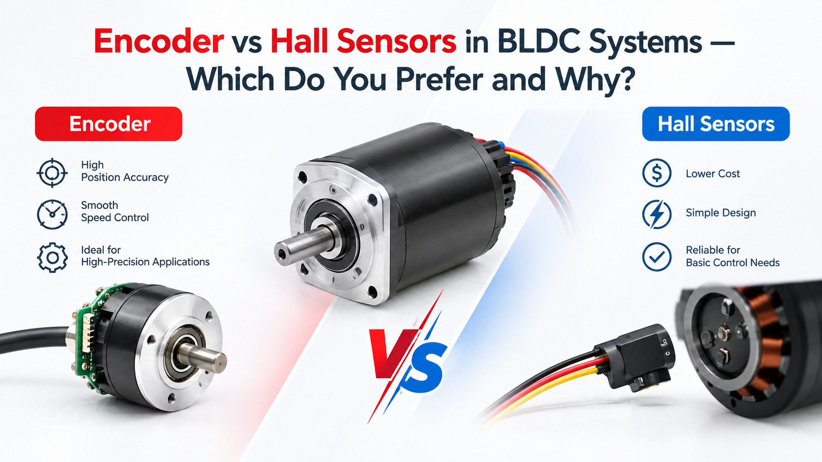
For most BLDC motor applications that primarily require reliable electronic commutation and basic speed feedback, Hall sensors are usually the preferred choice because they are simple, compact, cost-effective, and sufficiently accurate for six-step commutation. An encoder is preferable when the system requires substantially finer rotor-position information, accurate speed regulation, closed-loop position control, low-speed motion control, or advanced control such as high-performance field-oriented control (FOC).
The key engineering distinction is resolution rather than simply sensor type: a typical three-Hall BLDC motor provides six identifiable Hall states per electrical cycle, whereas an incremental encoder can provide many hundreds or thousands of counts per mechanical revolution, depending on its pulse specification and decoding method. The correct choice therefore depends on the motor’s pole-pair count, required speed range, positioning accuracy, controller architecture, and application dynamics.
Texas Instruments and university motor-control references describe Hall sensors as a practical method for determining rotor position for electronic commutation, while higher-resolution position feedback from encoders is generally more suitable when continuous rotor-angle information is required for precision control.
What Is the Difference Between a Hall Sensor and an Encoder?
A Hall sensor detects the magnetic field produced by the permanent-magnet rotor and generates a digital signal corresponding to rotor position. In a conventional three-phase BLDC motor, three Hall sensors commonly generate a combination of three digital signals that the controller uses to determine the appropriate phase-commutation sequence.
For a conventional six-step BLDC drive, the Hall-state sequence provides six valid commutation states during one electrical cycle. The controller uses these states to determine which motor phases should be energized.
The University of Texas at Austin’s motor-control material explains that BLDC motors use electronic commutation and that Hall signals or back-EMF can provide the rotor-angle information required for phase switching. The material also describes the six-state Hall sequence used during BLDC operation. University of Texas at Austin, Control Systems course material, accessed 2026.
An encoder, by comparison, provides substantially finer position information. Incremental encoders typically generate pulses as the shaft rotates, allowing the controller to calculate position, rotational speed, and direction from pulse frequency and phase relationship.
This distinction becomes important when the BLDC motor is used not simply to rotate a load, but to control exactly where, how fast, and how dynamically the load moves.
Hall Sensors vs Encoder: Engineering Comparison
| Parameter | Hall Sensor | Encoder |
| Primary function | Rotor position / commutation | Position and speed feedback |
| Typical output | Digital Hall states | Pulses / A-B channels, sometimes index |
| Position resolution | Low | Medium to very high |
| Six-step commutation | Excellent | Possible |
| Basic speed control | Good | Excellent |
| Precise position control | Limited | Excellent |
| Low-speed feedback | Limited resolution | Much better |
| Controller complexity | Low | Higher |
| Wiring | Usually simple | More signal connections |
| Cost | Lower | Higher |
| Mechanical integration | Compact | Requires additional integration |
| Typical applications | Fans, pumps, conveyors, general automation | Robotics, servo-like motion, precision positioning |
A 2017 IEEE conference study from Amrita Vishwa Vidyapeetham specifically notes that precision speed encoders can add substantial cost to a drive system, while Hall signals can provide a lower-cost method for BLDC speed and commutation feedback. Amrita Vishwa Vidyapeetham / IEEE ICCPCT, 2017.
When Should You Choose Hall Sensors?
Choose Hall sensors when commutation is the main requirement
If your controller primarily needs to know which electrical sector the rotor occupies, Hall sensors are often the most practical solution.
For example, a BLDC motor driving a pump may only require stable speed control rather than sub-degree shaft positioning. Adding a high-resolution encoder in such a system can increase cost, wiring, controller complexity, and integration effort without providing meaningful system-level benefits.
Hall sensors are particularly attractive for:
- Pumps and fans
- Electric lawn equipment
- Conveyors
- General industrial automation
- Electric bikes and mobility systems
- Solar tracking mechanisms
- Cost-sensitive OEM equipment
This is consistent with UNITED MOTION INC.’s BLDC motor portfolio, which supports Hall sensors for applications including industrial automation, robotics, electric mobility, solar tracking, pumps, and lawn equipment.
Hall sensors are also useful for startup
A major advantage of Hall feedback is that it provides rotor-position information even when the motor is stationary.
This is important because conventional sensorless BLDC control relies on back-EMF, which becomes difficult to detect at very low speed or zero speed.
A 2024 IEEE PEDES paper notes that back-EMF-based sensorless control can be difficult at low speeds, whereas position-sensor-based control provides direct rotor-position information. IEEE International Conference on Power Electronics, Drives and Energy Systems, 2024.
When Should You Choose an Encoder?
An encoder becomes more attractive when position accuracy and dynamic response are more important than minimum system cost.
Typical encoder applications include:
- Robotic joints
- AGVs and AMRs
- Precision positioning equipment
- Servo-like BLDC systems
- CNC-related motion systems
- Automated inspection equipment
- High-accuracy indexing mechanisms
The reason is straightforward: three Hall sensors divide the electrical cycle into relatively coarse position regions, while an encoder can provide much finer angular feedback.
For example, consider an incremental encoder rated at 1,000 pulses per revolution (PPR).
With simple single-edge counting:
1,000 pulses/revolution = 0.36° per pulse
If quadrature decoding uses four edges per cycle:
1,000 PPR × 4 = 4,000 counts/revolution
The theoretical count interval becomes:
360° / 4,000 = 0.09° per count
This does not mean the complete motion system will achieve 0.09° positioning accuracy, because backlash, bearing clearance, shaft torsion, encoder mounting error, controller latency, load inertia, and gearbox errors can all contribute to total positioning error.
This is one of the most common engineering mistakes: encoder resolution is not the same as system accuracy.
Encoder vs Hall Sensors for FOC Control
For basic six-step BLDC control, Hall sensors are usually sufficient because the controller primarily needs sector information.
For advanced field-oriented control (FOC), however, more continuous rotor-angle information can significantly improve control performance.
FOC transforms three-phase motor currents into a rotating d-q reference frame. Accurate rotor electrical angle is therefore important because an angle error can reduce torque-producing current alignment and increase current ripple or torque error.
A Texas A&M University research thesis discussing BLDC control notes that high-resolution rotor-position information can be obtained from an encoder or resolver, while Hall sensors provide substantially lower-resolution information. Texas A&M University, doctoral research, 2005–2006.
That does not mean every FOC BLDC motor requires an encoder. Modern controllers can estimate rotor position using observers, back-EMF, or other sensorless algorithms. However, when predictable low-speed behavior and precise rotor-angle feedback are required, an encoder remains a strong engineering option.
How to Select the Right Feedback Sensor: Step by Step
Step 1: Define the motion requirement
First determine whether the application requires:
- Commutation only
- Speed regulation
- Direction detection
- Position control
- High-accuracy positioning
If the requirement stops at commutation and moderate speed control, start with Hall sensors.
Step 2: Calculate the speed range
Determine minimum, continuous, and maximum RPM.
For example, a system operating from 300–3,000 RPM may have very different feedback requirements from a system operating from 1–100 RPM.
Low-speed applications generally benefit more from high-resolution feedback because each Hall transition represents a relatively large mechanical-angle interval.
Step3: Determine position accuracy
If the application requires only approximate positioning, Hall feedback may be adequate.
If the load must repeatedly stop within a narrow angular tolerance, an encoder should normally be considered.
Step 4: Check the controller
The motor, sensor, and controller must be treated as one system.
Verify:
- Hall logic sequence
- Encoder output type
- Supply voltage
- Maximum input frequency
- A/B phase relationship
- Electrical angle convention
- Commutation table
- Feedback interface
UNITED MOTION INC. specifically identifies Hall Sensor, Encoder Integration, and Driver Integration as BLDC motor customization options, which is important for OEM applications where the motor and controller need to be developed as a matched system.
Step 5: Consider environmental conditions
For industrial equipment, sensor selection should also consider:
- Temperature
- Vibration
- Dust
- Humidity
- Cable length
- EMI
- Connector reliability
- IP protection requirements
The sensor with the highest nominal resolution is not automatically the best sensor if its installation cannot survive the actual operating environment.
Common Troubleshooting Problems
| Problem | Likely Cause | Recommended Check |
| BLDC motor vibrates at startup | Incorrect Hall sequence | Verify Hall A/B/C sequence |
| Motor rotates backward | Incorrect phase or feedback sequence | Check phase-to-Hall relationship |
| Speed fluctuates | Poor feedback signal or controller tuning | Check sensor waveform and PWM settings |
| Motor overheats | Incorrect commutation angle or overload | Check Hall alignment, phase current and load |
| Encoder position drifts | Mechanical coupling or mounting error | Inspect shaft coupling and encoder fixation |
| Motor runs but has poor torque | Incorrect electrical angle | Verify Hall/encoder offset |
| Encoder counts are missing | EMI, wiring or excessive input frequency | Check shielding, grounding and controller limits |
| Low-speed motion is unstable | Feedback resolution too low | Consider encoder feedback |
A common mistake is replacing the motor immediately when the actual problem is a sensor-to-controller configuration error. Before changing hardware, engineers should verify the Hall sequence, encoder polarity, electrical offset, phase wiring, supply voltage, and controller parameters.
My Engineering Preference: Hall or Encoder?
For a standard industrial BLDC motor, I would normally choose Hall sensors first when the application requires reliable commutation, moderate speed regulation, and cost-effective integration.
I would choose an encoder when the application requires accurate position feedback, low-speed control, repeatable indexing, high dynamic response, or more precise closed-loop motion control.
In other words:
Hall sensors are primarily a practical commutation-feedback solution; encoders are primarily a precision motion-feedback solution.
The best engineering choice is therefore not determined by which sensor is technically “better,” but by whether the additional encoder resolution creates measurable value in the complete motor system.
Hall Sensor vs Encoder: Final Decision Guide
| Application Requirement | Recommended Feedback |
| Basic BLDC commutation | Hall sensor |
| Cost-sensitive motor | Hall sensor |
| Pump or fan | Hall sensor |
| Lawn equipment | Hall sensor |
| General automation | Hall sensor or encoder |
| Electric mobility | Hall sensor or encoder |
| Solar tracking | Hall sensor or encoder |
| Robotics | Encoder preferred |
| Precise positioning | Encoder |
| Low-speed precision motion | Encoder |
| Servo-like operation | Encoder |
| Advanced closed-loop control | Encoder preferred |
UNITED MOTION INC. offers BLDC motor solutions with 28–110 mm frame sizes, multiple voltage options, Hall sensor feedback, encoder integration, gearbox integration, and driver integration, allowing feedback selection to be matched to the actual mechanical and control requirements rather than forcing the same sensor architecture onto every application.
FAQ
Is an encoder better than a Hall sensor for a BLDC motor?
Not necessarily. Hall sensors are usually better for simple and cost-sensitive BLDC commutation, while encoders are better when high-resolution speed or position feedback is required.
Can a BLDC motor run with Hall sensors only?
Yes. A three-Hall BLDC motor can use Hall-state information for electronic commutation and closed-loop speed control.
Can a BLDC motor use both Hall sensors and an encoder?
Yes. Some systems use Hall sensors for robust commutation and an encoder for higher-resolution speed or position feedback, particularly in demanding motion-control applications.
How many Hall sensors does a BLDC motor normally use?
A conventional three-phase BLDC motor commonly uses three Hall sensors positioned around the stator to identify rotor position and determine the commutation sequence.
Are Hall sensors suitable for FOC?
They can be used with FOC, but their relatively coarse position information may limit performance compared with high-resolution encoder feedback. Advanced observers and estimation algorithms can also supplement Hall feedback.
Which sensor is better for low-speed BLDC control?
An encoder is generally preferable when very low-speed operation requires precise speed or position regulation because it provides substantially finer feedback resolution than conventional Hall-state sensing.
Related blog: Worm Gearbox vs Planetary Gearbox: Torque Comparison Guide