
Quick Answer
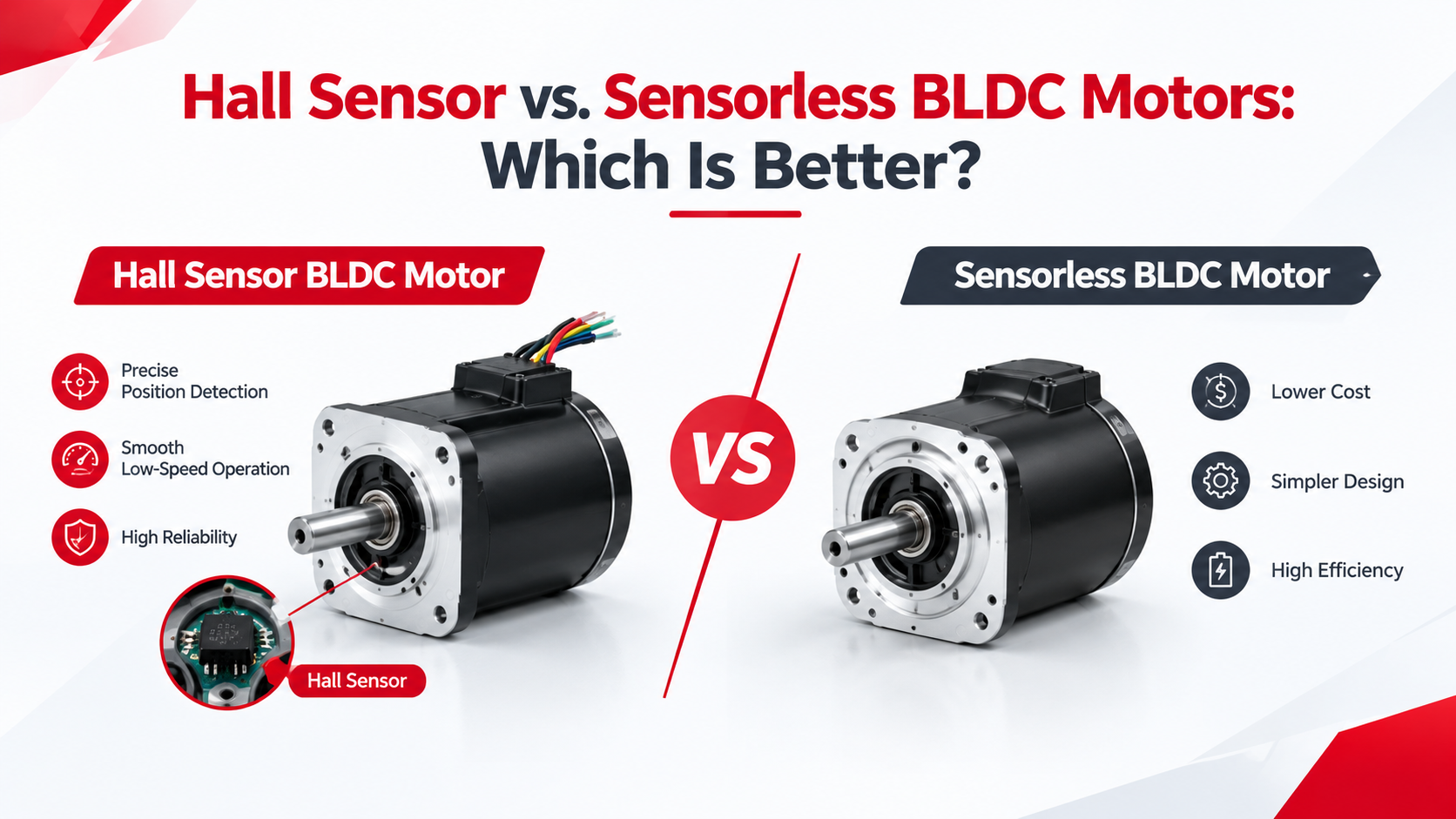
Hall sensor BLDC motors are generally better for applications requiring reliable startup, low-speed operation, and consistent rotor-position feedback, while sensorless BLDC motors are often better for applications that prioritize lower hardware cost, simpler wiring, and reduced component count.
The primary difference is how the motor controller detects rotor position. A Hall sensor BLDC motor uses physical magnetic sensors to identify the rotor’s position, while a sensorless BLDC motor estimates rotor position using electrical signals, commonly back electromotive force (back EMF).
For robotics, AGVs, actuators, and equipment that frequently starts under load, Hall sensor feedback can improve startup reliability and low-speed commutation. For fans, circulation pumps, and other applications operating mainly at moderate or high speeds, sensorless control may provide a more economical solution when the startup conditions are suitable.
The best choice depends on the application’s starting torque, operating speed, control requirements, environmental conditions, and total system cost—not simply whether the motor includes Hall sensors.
What Is a Hall Sensor BLDC Motor?
A Hall sensor BLDC motor uses magnetic sensors to detect the rotor’s position relative to the stator. In a typical three-phase BLDC motor, three Hall sensors provide digital signals that the controller uses to determine the appropriate commutation sequence.
As the rotor magnets move, the Hall signals change state, allowing the controller to energize the motor phases in the correct sequence and maintain rotation.
For conventional six-step commutation, three Hall signals typically identify six valid rotor-position sectors during each electrical cycle.
The main advantage is that rotor-position information is available even when the motor is stationary, which makes startup easier to manage and improves the reliability of conventional low-speed commutation.
Key advantages include:
– Reliable startup from standstill
– Better low-speed commutation
– More predictable operation under changing loads
– Straightforward rotor-position detection
– Compatibility with applications requiring frequent starts and stops
However, Hall sensors introduce additional components, wiring, connectors, and installation requirements, all of which must be considered during motor integration.
Engineering takeaway: Hall sensor feedback is particularly valuable when the controller must know the rotor’s position before the motor reaches a speed at which back EMF can be detected reliably.
What Is a Sensorless BLDC Motor?
A sensorless BLDC motor operates without dedicated Hall sensors for rotor-position detection. Instead, the controller estimates rotor position by analyzing electrical signals generated during motor operation.
A common approach uses back EMF, the voltage induced in the motor windings as the permanent-magnet rotor rotates. The controller monitors the electrical signal and uses the detected changes to determine when to commutate the motor phases.
This approach reduces the need for rotor-position sensors and associated wiring, making it attractive for applications where cost, space, and simplified integration are important.
The main advantages include:
– Fewer motor feedback wires
– Reduced sensor-related hardware
– Simpler motor assembly
– Lower sensor-related failure risk
– Potential cost savings in high-volume applications
The main limitation is startup performance. Because back EMF is extremely weak at standstill and low speed, conventional back-EMF-based sensorless control needs a startup sequence before reliable rotor-position estimation becomes possible.
If the motor must start under a heavy load, reverse rotation, or difficult mechanical conditions, the controller may struggle to establish stable commutation.
Engineering takeaway: Sensorless BLDC motors can be highly effective when the operating conditions suit the control algorithm, but removing Hall sensors does not eliminate the need for accurate rotor-position control.
Hall Sensor vs. Sensorless BLDC Motors: Key Differences
| Performance Factor | Hall Sensor BLDC | Sensorless BLDC |
| Rotor-position detection | Physical magnetic sensors | Estimated from electrical signals |
| Startup from standstill | Generally reliable | Depends on startup algorithm |
| Low-speed operation | Generally more reliable | More challenging with conventional back-EMF control |
| Starting under load | Often advantageous | Requires careful validation |
| High-speed operation | Suitable | Often suitable |
| Hardware cost | Higher sensor-related cost | Lower sensor-related cost |
| Wiring complexity | Additional sensor connections | Fewer feedback wires |
| Controller requirements | Hall-compatible commutation | Sensorless estimation and startup logic |
| Environmental considerations | Sensor and connector protection required | Fewer sensor-related components |
| Precision positioning | Hall feedback alone is limited | Back-EMF estimation alone is limited |
| Typical applications | Robotics, actuators, mobile equipment | Fans, selected pumps, continuous-speed systems |
These comparisons describe common implementations rather than universal rules. Advanced sensorless control methods can improve low-speed performance, while a poorly configured Hall sensor system can still experience startup problems, vibration, or incorrect commutation.
Which BLDC Motor Is Better for Your Application?
Robotics and AGV Drive Systems
Recommended starting point: Hall sensor BLDC motor.
Robots and automated guided vehicles frequently need to start from rest, accelerate smoothly, and respond to changing loads. Hall feedback provides rotor-position information during startup, making conventional commutation more predictable.
For applications requiring accurate positioning or sophisticated closed-loop motion control, an encoder may also be needed because conventional Hall signals provide relatively coarse rotor-position information.
Fans and Ventilation Systems
Recommended starting point: Sensorless BLDC motor.
Fans often operate continuously at moderate or high speeds, where back-EMF-based rotor-position estimation is practical. Eliminating Hall sensors can reduce wiring and component count.
However, engineers should evaluate startup torque, airflow-induced reverse rotation, and restart behavior before finalizing the design.
Pumps and Fluid Circulation Systems
Recommended starting point: Depends on the startup load.
A circulation pump with predictable startup conditions may work well with sensorless control. A pump that must start against substantial hydraulic resistance may benefit from Hall feedback if the sensorless startup algorithm cannot reliably handle the load.
Electric Lawn Equipment and Mobile Machinery
Recommended starting point: Hall sensor BLDC motor when startup consistency is critical.
Drive wheels, cutting mechanisms, and other load-dependent systems can experience frequent starts, variable resistance, and changing operating conditions. Hall feedback can improve startup consistency, although torque capability, thermal performance, environmental protection, and controller tuning remain equally important design considerations.
How to Choose the Right BLDC Motor?
Follow these five steps when selecting a motor for an OEM project.
Step 1: Define the operating requirements.
Identify the rated voltage, continuous torque, peak torque, rated speed, maximum speed, duty cycle, and expected operating life. Do not select a motor based on rated power alone.
Step 2: Evaluate startup conditions.
Determine whether the motor must start under load, operate at very low speeds, reverse direction frequently, or restart quickly after stopping. Difficult startup conditions often favor Hall feedback when conventional commutation is used.
Step 3: Match the motor and controller.
Confirm that the motor driver supports the required Hall signals or sensorless control algorithm, voltage range, continuous current, peak current, and speed range.
Step 4: Check mechanical integration.
Evaluate motor diameter, length, shaft configuration, mounting dimensions, gearbox requirements, and available installation space. If position feedback is required, determine whether Hall sensors provide sufficient resolution or an encoder is necessary.
Step 5: Validate the complete system.
Test startup under representative loads, minimum supply voltage, temperature extremes, and repeated start-stop cycles. For sensorless designs, verify that the controller can transition reliably from startup operation to stable commutation.
Common BLDC Motor Problems and Troubleshooting
| Problem | Possible Cause | Recommended Action |
| Hall motor vibrates but does not start | Incorrect phase wiring or Hall sequence | Verify phase connections and Hall signal order |
| Sensorless motor struggles to start | Weak initial rotor-position information | Review the startup sequence and current limits |
| Sensorless motor stalls at low speed | Back-EMF signal is too weak or noisy | Check minimum operating speed and control settings |
| Motor loses synchronization under load | Insufficient current or incorrect commutation timing | Review load torque, current limits, and controller tuning |
| Hall motor behaves inconsistently | Electrical interference or faulty sensor connections | Inspect wiring, grounding, and connectors |
| Motor overheats during repeated starts | Excessive current or prolonged startup | Review startup duration, current limits, and duty cycle |
The important distinction is that Hall feedback and sensorless control address rotor-position detection differently, but neither can compensate for an incorrectly selected motor, insufficient torque, unsuitable driver, or poorly designed mechanical system.
Common Engineering Mistakes
Choosing sensorless control solely to reduce cost. Sensorless designs reduce sensor-related hardware, but additional controller development, tuning, and troubleshooting can increase total project cost.
Assuming Hall sensors provide precise positioning. Hall sensors commonly used for BLDC commutation provide discrete position information rather than the high resolution required for many precision servo applications.
Ignoring startup torque. A motor that starts successfully without a load may fail when connected to a gearbox, wheel, pump, or actuator.
Ignoring the controller’s capabilities. Startup behavior, commutation stability, and speed regulation depend on the motor driver’s control algorithm as well as the motor’s electrical characteristics.
Assuming every sensorless method has the same limitations.
Conventional back-EMF detection and more advanced sensorless algorithms have different performance characteristics, so minimum speed and startup capability should be verified for the actual controller.
UNITED MOTION INC. BLDC Motor Solutions
UNITED MOTION INC. provides BLDC motor solutions across approximately 28–110 mm frame sizes, with customization options that can include Hall sensors, encoder integration, gearbox integration, integrated drivers, winding configurations, shaft designs, and mounting dimensions.
These options allow OEM engineers to select a motor configuration according to the application’s voltage, speed, torque, feedback, and installation requirements.
For example, a BLDC motor with Hall sensors may be suitable for an application requiring dependable startup and low-speed commutation, while a sensorless configuration may be more appropriate for a system where simplified wiring and reduced sensor-related hardware are priorities.
For applications requiring more advanced motion control, an encoder can provide higher-resolution position and speed feedback, while a gearbox can reduce output speed and increase available output torque. An integrated driver may further simplify electrical and mechanical integration.
UNITED MOTION INC. supports OEM motor customization for industrial automation, robotics, pumps, electric lawn equipment, and other motion-control applications.
Explore the UNITED MOTION INC. BLDC Motor page or contact our team for custom motor solutions.
FAQ
1. Is a Hall sensor BLDC motor better than a sensorless BLDC motor?
A Hall sensor motor is generally preferable when reliable startup, changing loads, and low-speed operation are important. A sensorless motor may be preferable when reducing hardware, wiring, and sensor-related costs is a priority.
2. Can a sensorless BLDC motor start from zero speed?
Yes. However, conventional back-EMF-based sensorless control requires a startup algorithm because back EMF cannot reliably indicate rotor position at standstill. Success depends on the motor, controller, and mechanical load.
3. Are sensorless BLDC motors more efficient?
Not necessarily. Overall efficiency depends on the motor’s electrical design, controller, commutation strategy, operating speed, and load. Removing Hall sensors does not automatically increase motor efficiency.
4. Do Hall sensor BLDC motors work at low speed?
Yes. Hall sensors can provide rotor-position information at low speeds and standstill, making them useful for applications requiring dependable conventional BLDC commutation.
5. Can Hall sensors be replaced with an encoder?
An encoder can provide higher-resolution position and speed feedback, but the motor controller must support the encoder’s signal type and interface. An encoder is often more appropriate when precise positioning or advanced closed-loop motion control is required.
6. How do I select the right BLDC motor for an OEM application?
Start by defining voltage, torque, speed, startup load, duty cycle, and control accuracy. Then select the feedback method, motor dimensions, gearbox, encoder, and driver according to the complete system requirements.