
Quick Answer
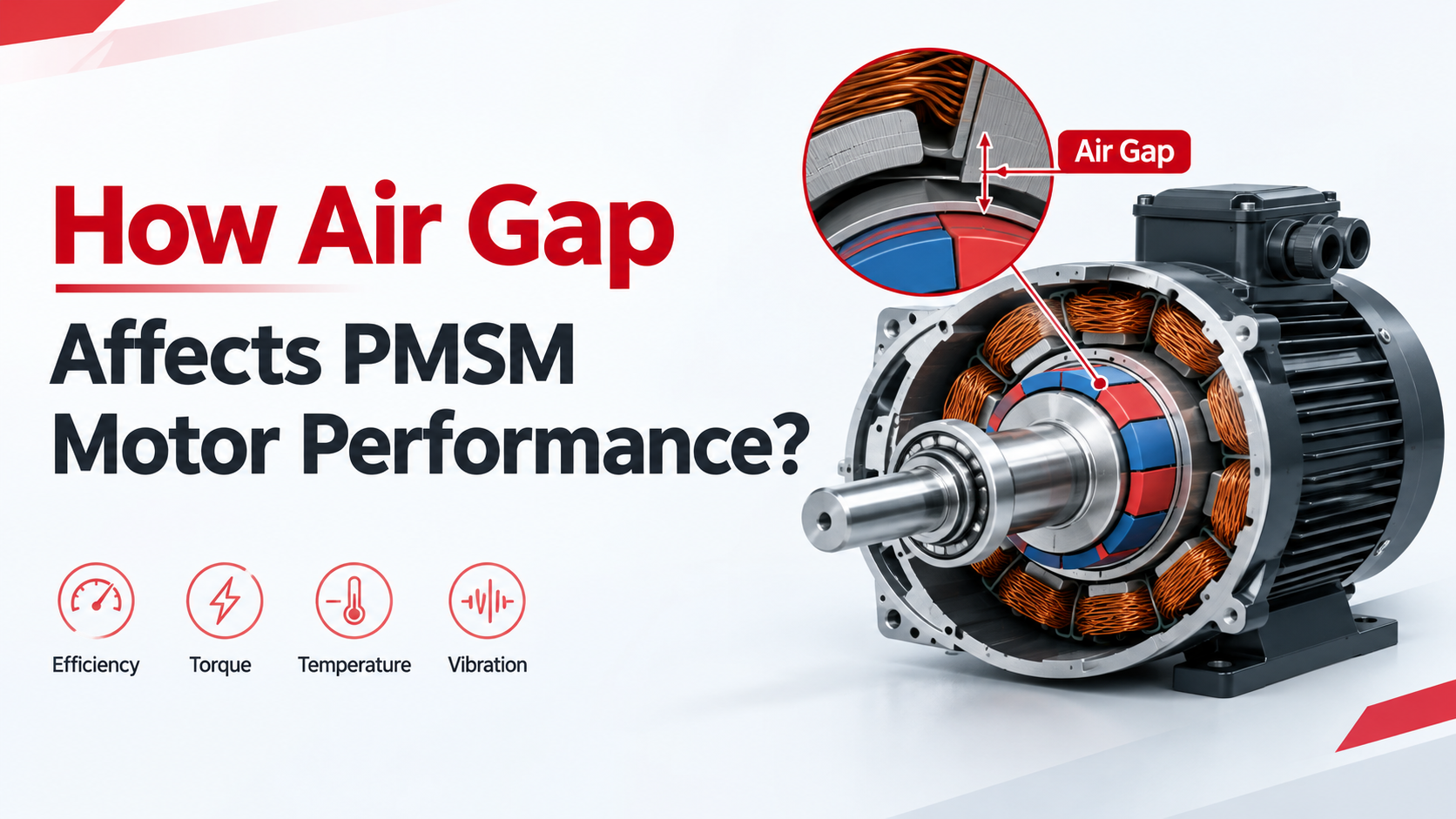
The air gap is one of the most important design parameters in a Permanent Magnet Synchronous Motor (PMSM) because it directly affects magnetic flux, torque, back EMF, efficiency, torque ripple, vibration, and mechanical reliability.
In general, reducing the air gap improves magnetic coupling between the rotor permanent magnets and stator, which can increase torque density and torque per ampere. However, an excessively small air gap makes the motor more sensitive to rotor eccentricity, bearing tolerance, shaft runout, thermal expansion, and manufacturing variation.
A larger air gap provides more mechanical clearance and can improve manufacturing tolerance, but it generally reduces magnetic coupling and may require stronger magnets, a larger magnetic circuit, or higher current to achieve the same torque.
The key engineering principle is simple: the best PMSM air gap is not necessarily the smallest possible air gap; it is the gap that provides the required electromagnetic performance while maintaining sufficient mechanical reliability.
What Is the Air Gap in a PMSM?
The air gap is the small radial space between the rotor and stator of a radial-flux PMSM.
Inside the motor, the permanent magnets mounted on the rotor generate magnetic flux that passes across this gap and enters the stator. Because air has much higher magnetic reluctance than the steel components used in the magnetic circuit, even a relatively small change in air-gap length can significantly influence the motor’s magnetic performance.
For this reason, air-gap design cannot be considered only a mechanical clearance issue. It is also an important electromagnetic design parameter.
When engineers develop a PMSM, the air gap is normally evaluated together with:
- Rotor diameter
- Stator inner diameter
- Permanent magnet thickness
- Magnet arc
- Pole count
- Slot count
- Stator tooth geometry
- Winding configuration
- Motor speed
- Required torque
Source: PMSM motor engineering design principle
How Does Air Gap Affect PMSM Motor Performance?
Air Gap and Motor Torque
One of the most important effects of air gap is its influence on electromagnetic torque.
When the air gap becomes smaller within a practical design range, the rotor magnets can couple more effectively with the stator magnetic circuit. This generally increases the useful magnetic flux available for producing torque.
As a result, a properly optimized smaller air gap can provide:
- Higher torque density
- Higher torque per ampere
- Better utilization of permanent magnets
- More compact motor dimensions
This is especially important when designing motors for applications where installation space is limited but substantial output torque is required, including robotics, AGVs, industrial automation, medical equipment, stairlift systems, pumps, and electric lawn equipment.
However, reducing the air gap does not provide unlimited torque improvement. Once parts of the magnetic circuit approach saturation, additional magnetic flux produces progressively smaller performance benefits.
Air Gap and Back EMF
The air gap also affects the motor’s back electromotive force (back EMF).
Back EMF is the voltage generated by the motor when the permanent-magnet rotor rotates. It is an important parameter when selecting the motor voltage, operating speed, and motor driver.
A smaller practical air gap generally produces stronger magnetic coupling and therefore higher back EMF at the same rotational speed.
A larger air gap generally reduces effective magnetic flux and therefore tends to reduce back EMF.
This relationship becomes particularly important in high-speed BLDC and PMSM motors, because excessive back EMF at high speed can reduce the available voltage margin of the motor driver.
For OEM motor development, engineers therefore need to evaluate air gap together with:
- DC bus voltage
- Maximum speed
- Motor winding
- Permanent magnet strength
- Driver voltage capability
- Control strategy
Small Air Gap vs. Large Air Gap
| Performance Factor | Smaller Air Gap | Larger Air Gap |
| Magnetic coupling | Generally higher | Generally lower |
| Air-gap flux | Generally higher | Generally lower |
| Torque density | Higher potential | Lower potential |
| Torque per ampere | Higher potential | Lower potential |
| Back EMF | Higher potential | Lower potential |
| Mechanical clearance | Lower | Higher |
| Manufacturing tolerance | More demanding | More forgiving |
| Rotor eccentricity sensitivity | Higher | Lower |
| Rotor-stator contact risk | Higher | Lower |
| Magnet utilization | Generally better | Generally lower |
| Design complexity | Higher | Lower |
These are general engineering trends. Actual results depend on the PMSM topology, rotor structure, magnet material, stator design, winding configuration, operating speed, and motor controller.
Does a Smaller Air Gap Always Improve Efficiency?
No.
A smaller air gap can improve magnetic coupling and allow the motor to produce the required torque with lower current. Lower current can potentially reduce copper losses and improve overall efficiency.
However, an excessively small air gap can introduce other problems.
These may include:
- Magnetic saturation
- Increased iron loss
- Higher torque ripple
- Greater cogging torque
- Increased electromagnetic noise
- Higher sensitivity to manufacturing tolerances
- Greater risk of rotor-stator contact
Therefore, engineers should not optimize the air gap solely for maximum magnetic flux.
The correct approach is to find the best balance between torque, efficiency, thermal performance, acoustic behavior, manufacturing tolerance, and mechanical reliability.
Air Gap and Torque Ripple
Air-gap geometry also affects the distribution of magnetic flux between the rotor and stator.
If the magnetic field is not sufficiently uniform, the motor can experience:
- Cogging torque
- Torque ripple
- Electromagnetic vibration
- Acoustic noise
- Low-speed speed fluctuation
These effects can become particularly important in precision applications.
For example, a motor used in a servo system may need very smooth low-speed operation, while a lawn mower drive motor may place greater emphasis on torque, efficiency, noise, and overload capability.
Therefore, the optimum air gap depends heavily on the application requirements, rather than simply the motor’s rated power.
How Engineers Determine the Correct PMSM Air Gap?
Step 1: Define the Application Requirements
Engineers first establish the complete operating requirements, including:
- Rated voltage
- Rated speed
- Maximum speed
- Continuous torque
- Peak torque
- Duty cycle
- Ambient temperature
- Installation space
- Noise requirements
- Expected service life
A motor operating continuously at 3,000 rpm, for example, requires a different design balance from a motor that operates intermittently at 500 rpm.
Step 2: Design the Magnetic Circuit
The air gap must be considered together with the complete electromagnetic structure.
Engineers evaluate:
- Rotor diameter
- Stator diameter
- Magnet thickness
- Magnet arc
- Pole count
- Slot count
- Stator tooth width
- Stack length
- Winding configuration
Changing the air gap may require changes to other motor dimensions.
Step 3: Use Electromagnetic Simulation
Finite Element Analysis (FEA) can be used to compare different air-gap configurations before building prototypes.
Typical evaluation parameters include:
- Air-gap magnetic flux
- Electromagnetic torque
- Back EMF
- Torque ripple
- Cogging torque
- Stator saturation
- Magnet demagnetization margin
- Core loss
Instead of selecting one theoretical air gap, engineers can compare several candidate designs and identify the best overall performance.
Source: Motor electromagnetic simulation and engineering design practice
Manufacturing Tolerance Is Critical
One common mistake is designing a PMSM around the nominal air gap only.
The actual production air gap can be affected by:
- Rotor eccentricity
- Bearing clearance
- Shaft runout
- Rotor balancing
- Lamination tolerance
- Magnet positioning
- Housing tolerance
- Thermal expansion
For example, if a motor is designed with an extremely small nominal air gap, even a small amount of rotor eccentricity can significantly reduce the clearance at one location.
This is why engineers need to consider both the nominal air gap and minimum operating clearance.
A motor that performs well in simulation may still experience rotor-stator interference if manufacturing tolerances are not properly controlled.
Common PMSM Air-Gap Problems
| Problem | Possible Cause | Engineering Check | Potential Solution |
| Low torque | Air gap too large | Measure actual air gap | Re-optimize magnetic circuit |
| High motor current | Insufficient magnetic coupling | Check magnetic flux | Optimize magnet and air-gap design |
| Excessive back EMF | Excessive magnetic flux | Perform no-load voltage test | Rebalance magnet and air-gap design |
| High torque ripple | Uneven magnetic field | Perform FEA analysis | Optimize rotor/stator geometry |
| Rotor rubbing | Insufficient mechanical clearance | Check rotor eccentricity | Increase minimum clearance |
| High vibration | Rotor eccentricity | Measure shaft runout | Improve rotor/bearing tolerance |
| High temperature | Excessive current or saturation | Check current and thermal performance | Optimize magnetic loading |
| Poor efficiency | Excessive copper/core losses | Test efficiency at multiple loads | Rebalance electromagnetic design |
Common Engineering Mistakes
Mistake 1: Making the Air Gap as Small as Possible
A smaller air gap can improve magnetic performance, but it also reduces mechanical clearance and increases sensitivity to manufacturing tolerances.
Better approach: optimize the air gap based on electromagnetic performance and the complete mechanical tolerance stack.
Mistake 2: Looking Only at Rated Torque
OEM applications rarely operate at exactly one operating point.
Engineers should also consider:
- Starting torque
- Acceleration torque
- Peak torque
- Continuous torque
- Low-speed performance
- Maximum speed
- Thermal conditions
Mistake 3: Ignoring the Motor Driver
The PMSM or BLDC motor should be evaluated together with its controller, particularly when using FOC (Field-Oriented Control).
The motor’s back EMF, inductance, speed range, current requirements, and driver voltage should all be compatible.
Mistake 4: Ignoring Temperature
Thermal expansion can change the effective mechanical clearance between rotor and stator.
This is particularly important for high-speed motors and applications with significant temperature variation.
Air Gap in BLDC and PMSM Motor Applications
PMSM and BLDC motors share many fundamental permanent-magnet motor principles, although their back-EMF waveforms, commutation methods, and control strategies can differ.
For OEM applications, air-gap optimization should therefore be considered as part of the complete motor design rather than as an isolated parameter.
UNITED MOTION INC. provides BLDC motor solutions covering approximately Φ28–Φ110 mm, with customization options including:
- Gearboxes
- Encoders
- Integrated drivers
- Customized voltage
- Customized torque
- Customized speed
- Application-specific motor configurations
These options allow a BLDC motor manufacturer to adapt the motor system to different industrial requirements rather than relying on a one-size-fits-all motor.
For example, adding a gearbox can provide higher output torque and lower output speed, while an encoder can provide speed and position feedback for closed-loop motion control. An integrated driver can further simplify system integration where space and wiring requirements are important.
This makes air-gap optimization one part of a broader custom electric motor and motion control solution.
How to Optimize Air Gap for an OEM Motor?
A practical OEM development process can follow this sequence:
Application requirements → Motor geometry → Air-gap design → Electromagnetic simulation → Prototype → Performance testing → Tolerance validation → Mass production
Prototype testing should evaluate:
- No-load back EMF
- Torque-speed performance
- Efficiency
- Phase current
- Temperature rise
- Vibration
- Acoustic noise
- Torque ripple
- Mechanical clearance
This approach is more reliable than selecting an air gap from a generic specification because the optimum value depends on the complete electromagnetic and mechanical architecture.
For OEM customers, working directly with a BLDC motor supplier or custom motor manufacturer can also simplify the process of matching motor geometry, gearbox ratio, encoder configuration, driver requirements, and application performance.
FAQ
What happens if the PMSM air gap is too large?
A larger air gap generally reduces magnetic coupling between the rotor and stator, which can reduce torque density and back EMF and may require higher current or additional magnet material.
Does a smaller air gap always improve PMSM efficiency?
No. A smaller air gap can improve magnetic coupling, but an excessively small gap can increase saturation, torque ripple, electromagnetic losses, manufacturing sensitivity, and mechanical risk.
What is a typical PMSM air gap?
There is no single standard PMSM air-gap value. The appropriate value depends on motor diameter, rotor structure, magnet configuration, operating speed, manufacturing capability, and required mechanical clearance.
How does air gap affect PMSM back EMF?
A smaller practical air gap generally increases magnetic coupling and can increase back EMF, while a larger air gap generally reduces effective magnetic flux and back EMF.
How does air gap affect PMSM torque?
Reducing the air gap within a practical design range generally improves magnetic coupling and can increase torque per ampere, although the benefit becomes limited when magnetic saturation and other design constraints become significant.
Can the air gap be customized for an OEM motor?
Yes. Air-gap design can be optimized as part of a custom electric motor project together with the permanent magnets, stator, winding, rotor, gearbox, encoder, and integrated driver.
Related blog: How Magnet Shape Affects PMSM Motor Performance?