
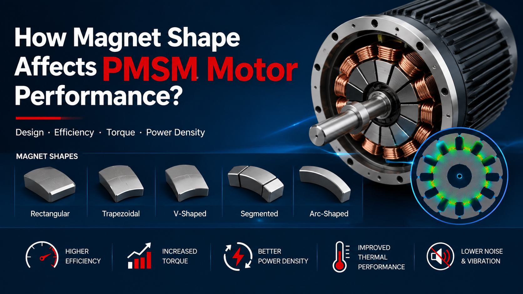
The shape of the permanent magnets has a direct influence on PMSM motors because it determines how magnetic flux is distributed across the air gap. Parameters such as magnet arc width, thickness, curvature, segmentation, and magnetization direction affect average torque, cogging torque, torque ripple, back EMF, efficiency, vibration, and high-speed operating capability.
A larger magnet does not necessarily mean a better PMSM. Increasing magnet volume may increase magnetic flux, but it can also increase cogging torque, back EMF, leakage flux, and local iron saturation. Therefore, PMSM magnet geometry should be optimized together with the stator winding, air gap, slot-pole combination, and inverter control strategy.
Research published in Electric Power Systems Research demonstrated that changing magnet arc width could substantially reduce cogging torque and torque ripple while maintaining practical torque output.
Magnet Arc Width
The pole-arc ratio, which represents magnet arc width relative to pole pitch, is one of the most important PMSM rotor parameters.
A larger pole arc generally increases the effective magnetic coverage and can increase fundamental air-gap flux. However, excessive magnet coverage increases interaction between the rotor magnetic field and stator-slot permeance, potentially increasing cogging torque and harmonic distortion.
Published research has shown that reducing magnet arc can significantly reduce cogging torque and total torque ripple, although excessive reduction may reduce average torque and back EMF.
Therefore, the optimum pole-arc ratio is a compromise between torque density, cogging torque, and waveform quality.
Magnet Thickness
Magnet thickness determines the available magnetomotive force and strongly affects air-gap flux.
Increasing magnet thickness can increase torque and back EMF, but the relationship is not linear because the magnetic circuit contains the air gap, stator teeth, rotor iron, and leakage paths.
Once the magnetic circuit approaches saturation, additional magnet material provides progressively smaller benefits while increasing material cost and rotor mass.
For this reason, designers normally optimize magnet thickness together with:
- Air-gap length
- Stator-tooth width
- Rotor back-iron thickness
- Magnet grade
- Operating temperature
- Demagnetization margin
The U.S. Department of Energy’s electric-motor R&D programs emphasize efficiency, power density, cost, weight, and reduced dependence on critical materials as important motor-design objectives.
Curved and Special-Shaped Magnets
Instead of using a simple rectangular magnet, PMSM rotors can use arc-shaped, curved, bread-loaf, stepped, or specially profiled magnets.
The primary objective is to control the air-gap flux-density waveform.
A properly optimized magnet profile can reduce selected harmonic components and consequently decrease:
- Cogging torque
- Torque ripple
- Electromagnetic vibration
- Acoustic noise
- Additional iron losses
Research published by Elsevier has shown that permanent-magnet geometry optimization can reduce cogging torque while maintaining required torque output.
For IPMSM designs, magnet placement and shape can also influence reluctance torque, flux concentration, mechanical strength, and field-weakening capability.
Magnet Shape and Cogging Torque
Cogging torque results from the interaction between permanent-magnet flux and the varying magnetic reluctance caused by stator slots and teeth.
Because cogging torque exists even when the stator current is zero, it is particularly important in low-speed servo systems, robotics, positioning equipment, and other applications requiring smooth rotation.
Magnet arc optimization, segmentation, skewing, and edge shaping are commonly used to reduce this effect.
However, reducing cogging torque should not be treated as the only optimization objective, because a geometry that produces very low cogging torque may simultaneously reduce average torque or increase manufacturing complexity.
PMSM Magnet Shape Comparison
| Large magnet arc | Higher flux coverage | Higher torque potential | Higher cogging torque |
| Small magnet arc | Lower flux interaction | Reduced cogging torque | Lower torque capability |
| Thick magnet | Higher PM flux | Higher torque/back EMF | Cost and saturation |
| Curved magnet | Improved flux distribution | Lower harmonics | More complex manufacturing |
| Segmented magnet | Harmonic control | Reduced losses/ripple | Assembly complexity |
| Optimized IPM magnet | Flux concentration | Torque + field weakening | More comp |
Step-by-Step Magnet Optimization
Step 1: Define the motor requirements
Start with rated torque, maximum torque, rated speed, maximum speed, DC-bus voltage, current limit, efficiency target, and operating temperature.
Step 2: Establish the baseline rotor
Define magnet thickness, pole-arc ratio, air gap, magnet material, and magnetization direction.
Step 3: Use electromagnetic FEA
Evaluate average torque, cogging torque, torque ripple, back EMF, flux linkage, iron loss, and demagnetization margin.
Step 4: Optimize the geometry
Sweep magnet arc, thickness, curvature, and edge profile rather than optimizing only one parameter.
For preliminary studies, designers may evaluate pole-arc ratios around 0.65–0.95, but the appropriate range depends heavily on the slot-pole combination and motor topology.
Step 5: Validate at multiple operating points
A magnet design that performs well at rated speed may create excessive back EMF at maximum speed or insufficient field-weakening margin, so testing should cover the complete operating envelope.
Common Engineering Problems
| Problem | Possible cause | Recommended approach |
| High cogging torque | Excessive magnet arc | Optimize pole-arc ratio |
| High torque ripple | Strong magnetic harmonics | Modify magnet profile |
| Low torque | Insufficient effective flux | Optimize magnet arc/thickness |
| Excessive back EMF | Excessive PM flux | Reduce magnet volume or optimize geometry |
| High iron loss | Harmonic flux | Improve magnet shape and edge profile |
| Rotor heating | Magnet eddy-current loss | Use segmentation and reduce harmonics |
Practical Engineering Insight
The key principle is that magnet shape should be optimized as part of the complete PMSM electromagnetic system, not independently.
The same magnet geometry can produce different results when used with different slot-pole combinations, air gaps, windings, or control strategies. Therefore, simply increasing magnet size is rarely the most effective way to improve PMSM performance.
For OEM motor development, a practical design process combines analytical calculations, electromagnetic FEA, thermal analysis, mechanical validation, and prototype testing before finalizing the rotor geometry.
FAQ
Does a larger magnet always increase PMSM torque?
No. Increasing magnet volume can increase magnetic flux, but saturation, leakage flux, voltage limits, and thermal constraints can reduce the additional benefit.
Which magnet shape is best for PMSM motors?
There is no universal best shape. Curved, segmented, stepped, bread-loaf, and IPM magnet geometries can each be effective depending on the motor’s torque, speed, efficiency, and noise requirements.
Can magnet shape reduce cogging torque?
Yes. Optimizing magnet arc width, edge shape, segmentation, and skew can significantly reduce cogging torque.
Does magnet shape affect PMSM efficiency?
Yes. Magnet geometry affects flux harmonics, iron losses, torque production, back EMF, and therefore overall motor efficiency.
Is FEA necessary for PMSM magnet optimization?
For production-level design, electromagnetic FEA is strongly recommended because it can evaluate saturation, leakage flux, harmonics, cogging torque, torque ripple, and demagnetization risk.
Related blog: Compare PMSM vs Induction Motor Performance for EV