
Quick Answer
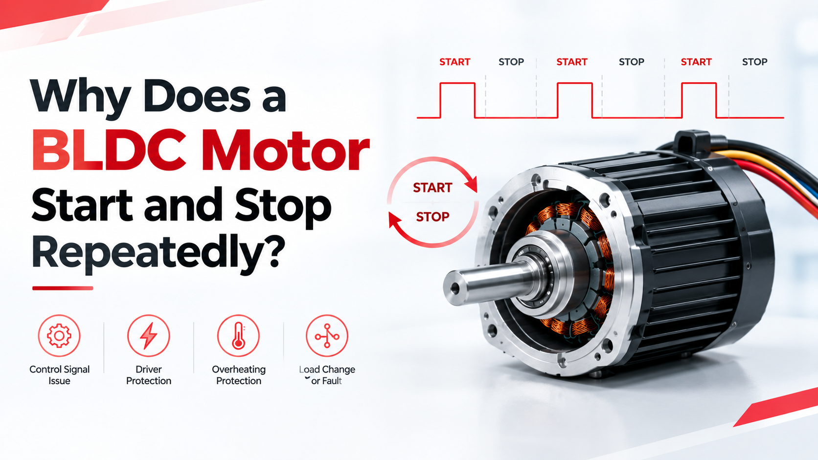
A BLDC motor that starts and stops repeatedly is usually experiencing unstable power supply, controller protection, faulty Hall sensor feedback, excessive mechanical load, overheating, or an incorrect control signal. When the fault temporarily disappears, the controller may attempt to restart the motor, creating a repeated start-stop cycle.
In robotic lawn mower applications, common causes include battery voltage drops during acceleration, wheels blocked by grass or debris, loose electrical connectors, excessive wheel resistance, and motor-controller settings that do not match the application’s load requirements.
The most effective troubleshooting approach is to determine whether the motor stops because its power supply becomes unstable, the controller disables its output, the rotor cannot accelerate, or the motor’s feedback signals become unreliable.
Engineering principle: Diagnose the complete motor-drive system before replacing the motor, because the same symptom can originate from the power supply, controller, wiring, motor, or mechanical assembly.
What Causes a BLDC Motor to Start and Stop Repeatedly?
Unstable Power Supply or Battery Voltage Drop
A BLDC motor generally draws substantial current during startup and acceleration because it must overcome rotor inertia, mechanical friction, and the connected load. If the battery is discharged, the power supply has insufficient current capacity, or an electrical connection has excessive resistance, the voltage at the motor controller may drop below its operating threshold.
The controller may then stop driving the motor. When the supply voltage recovers, it may attempt another startup, producing repeated cycling.
How to troubleshoot:
– Measure the supply voltage directly at the controller terminals during startup.
– Inspect battery terminals, connectors, fuses, and ground-return wiring.
– Check whether voltage drops coincide with the motor stopping.
– Confirm that the power supply supports the required continuous and peak current.
– Compare measured voltage with the motor and controller specifications.
For example, a nominal 24 V motor system must be evaluated against the controller’s actual operating-voltage range and undervoltage threshold, because a battery displaying an acceptable voltage at rest may still experience significant voltage sag during acceleration.
Motor Controller Overcurrent Protection
A motor controller may interrupt operation when phase current exceeds its configured limit or when the motor cannot accelerate as expected.
For a robotic lawn mower hub motor, excessive grass density, steep slopes, a blocked wheel, bearing friction, or an unsuitable drive configuration can increase the required torque and cause the controller to trigger overcurrent protection.
Repeated restarting does not necessarily mean the motor is defective; the controller may be protecting the electrical and mechanical system from excessive load.
Recommended checks:
1. Read the controller fault code immediately after the motor stops.
2. Inspect the wheel, hub, bearings, and transmission components.
3. Compare startup current with the controller’s configured current limit.
4. Verify continuous and peak torque requirements under actual operating conditions.
5. Confirm that the motor and controller are correctly matched.
Hall Sensor or Motor Wiring Faults
Many sensored BLDC motors use three Hall sensors to provide rotor-position information for electronic commutation. If a Hall signal becomes intermittent because of loose connectors, damaged wiring, electrical interference, or incorrect configuration, the controller may lose reliable rotor-position information.
Typical symptoms include jerky startup, irregular rotation, sudden stopping, vibration, and failure to start under load.
Inspect the Hall sensor supply, signal wiring, connector pinout, and phase connections. Confirm that the controller configuration matches the motor’s electrical arrangement.
Avoid randomly exchanging phase wires or Hall sensor connections, because incorrect combinations can cause poor commutation, excessive current, or failure to start.
Motor or Controller Overheating
A BLDC motor may operate normally when cold but stop after several minutes as the winding or controller temperature rises. If the controller reaches its thermal protection threshold, it may reduce output or shut down until the temperature falls.
Possible causes include prolonged overload, high ambient temperature, insufficient cooling, excessive current, or an unsuitable motor-driver combination.
Measure motor and controller temperatures during the actual duty cycle. If the motor consistently stops after a similar operating period, investigate thermal protection, cooling conditions, current loading, and installation design before changing the motor.
BLDC Motor Start-Stop Troubleshooting Table
| Symptom | Possible Cause | Recommended Check |
| Stops during acceleration | Voltage sag or overcurrent | Monitor supply voltage and startup current |
| Starts, jerks, then stops | Hall sensor or phase wiring fault | Inspect wiring and sensor signals |
| Stops when the wheel encounters thick grass | Mechanical overload | Inspect wheel resistance and load |
| Runs for several minutes, then stops | Thermal protection | Monitor motor and controller temperature |
| Restarts after power cycling | Controller fault or protection reset | Record fault codes before resetting |
| Stops intermittently on rough terrain | Loose connector or damaged wiring | Inspect the harness and connections |
| One wheel stops more frequently | Unequal mechanical load or drive-channel fault | Compare wheel resistance and current |
| Motor does not restart immediately | Thermal delay or latched protection | Check controller status and restart conditions |
These symptoms are diagnostic clues rather than definitive fault identifications. Confirm the root cause through measurements and controller diagnostics before replacing components.
How to Troubleshoot a BLDC Motor Step by Step
Step 1: Identify When the Motor Stops
Record whether the motor stops immediately during startup, during acceleration, under heavy load, or after prolonged operation. This helps distinguish electrical problems from mechanical overload and thermal protection.
Step 2: Check Supply Voltage and Current
Measure the controller input voltage during startup and immediately before shutdown. Monitor current where appropriate and compare the results with the motor, battery, wiring, and controller ratings.
Step 3: Inspect Mechanical Resistance
With the equipment powered off and made safe, inspect the wheel, hub, bearings, and gearbox where fitted. Look for trapped grass, foreign objects, binding, damaged components, or abnormal friction.
Step 4: Check Controller Fault Codes
Review status indicators, diagnostic software, and fault history. Prioritize undervoltage, overcurrent, Hall sensor, locked-rotor, and overtemperature faults.
Step 5: Verify Motor-Controller Compatibility
Confirm that the rated voltage, phase current, peak current, Hall sensor configuration, commutation settings, and speed-control signals are compatible.
Step 6: Repeat the Test Under Realistic Conditions
After correcting the suspected fault, repeat the startup and load tests while monitoring current, voltage, temperature, and rotation. A successful no-load test does not prove that the system can handle actual mowing conditions.
Why Robotic Lawn Mower Hub Motors Need Special Attention?
A robotic lawn mower hub motor operates under changing terrain, wheel loads, grass conditions, moisture exposure, and repeated acceleration and deceleration. These conditions create load variations that may not appear during a stationary laboratory test.
When selecting a hub motor for an OEM robotic mower, engineers should evaluate:
– Continuous and peak torque requirements
– Wheel diameter and total vehicle mass
– Maximum slope and traction requirements
– Startup current and controller current limits
– Hub bearing capacity and mechanical sealing
– Water and dust protection requirements
– Thermal performance during extended operation
– Battery and motor-controller compatibility
For example, a hub motor that performs adequately on flat, dry ground may experience current-limit events when the mower climbs a slope or enters dense grass. The solution may involve optimizing the motor torque, wheel design, controller settings, or mechanical system rather than simply selecting a motor with a higher rated power.
For outdoor equipment, engineers should also evaluate cable routing, connector retention, vibration resistance, and protection against moisture and debris, because intermittent electrical connections can produce symptoms similar to motor failure.
Common Engineering Mistakes
Replacing the motor before checking the controller: A faulty power supply, damaged connector, or controller fault can produce the same symptoms as a defective motor.
Increasing the current limit without checking the load: This can expose the motor windings, controller power stage, wiring, and battery to excessive current.
Testing only without a mechanical load: A motor may run smoothly on a bench but fail when wheel torque increases during acceleration or climbing.
Resetting faults without recording them: Power cycling can temporarily hide an intermittent problem or erase useful diagnostic information.
Ignoring environmental conditions: Moisture, corrosion, vibration, and temperature cycling can cause intermittent connector or sensor problems in outdoor equipment.
How UNITED MOTION INC. Supports OEM Motor Applications?
UNITED MOTION INC. provides BLDC motor solutions for industrial and OEM applications, with available configurations that can include gearboxes, encoders, and integrated drivers.
For robotic lawn mower development, motor selection should begin with the actual vehicle mass, wheel diameter, target speed, slope capability, operating time, and peak load rather than rated power alone.
A suitable motor-drive system should be evaluated as a complete assembly, including torque-speed characteristics, controller current limits, thermal performance, mechanical integration, and environmental requirements.
For a custom robotic lawn mower hub motor, sharing the application load profile, operating voltage, controller specifications, and required wheel performance with the motor supplier can help identify whether repeated stopping originates from motor sizing, drive configuration, mechanical resistance, or protection settings.
Explore our BLDC motor solutions or contact UNITED MOTION INC. to discuss OEM motor requirements.
FAQ
Why does my BLDC motor start and stop every few seconds?
Common causes include undervoltage, overcurrent protection, faulty Hall sensor signals, unstable control commands, and mechanical overload. Check the controller fault codes and monitor supply voltage and current during startup.
Can a weak battery cause a BLDC motor to keep restarting?
Yes. If battery voltage drops below the controller’s operating threshold during acceleration, the controller may disable the motor and attempt to restart when the voltage recovers.
Can a faulty Hall sensor make a BLDC motor stop intermittently?
Yes. An intermittent Hall signal can prevent reliable rotor-position detection and commutation, resulting in jerky operation, startup failure, or shutdown.
Why does a robotic lawn mower hub motor stop in thick grass?
Dense grass or difficult terrain can increase wheel resistance and required torque. The resulting current demand may trigger controller overload protection if it exceeds the system’s configured limits.
Should I increase the motor controller’s current limit?
Not before identifying the cause. First verify mechanical load, motor ratings, wiring, battery capability, and controller specifications. Increasing the limit without validating these factors can damage the drive system.
How can I prevent repeated BLDC motor shutdowns?
Use a correctly matched motor and controller, maintain stable power delivery, inspect wiring and mechanical components, configure protection limits appropriately, and validate performance under realistic operating conditions.