
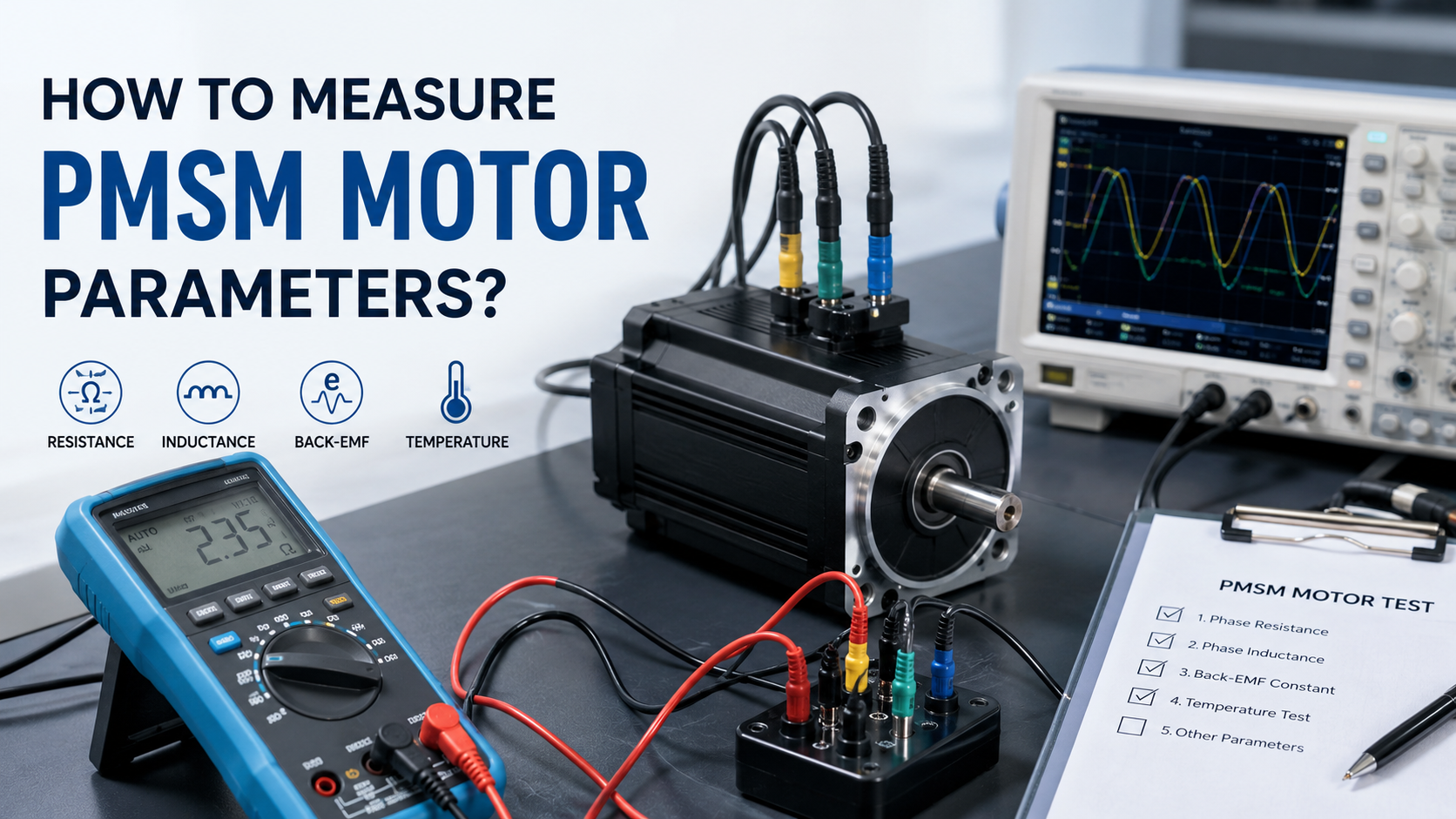
Accurate PMSM motor parameter measurement is essential for motor control tuning, field-oriented control (FOC), efficiency optimization, and system commissioning. The most important parameters include stator resistance (Rs), d-axis and q-axis inductance (Ld/Lq), back EMF constant (Ke), flux linkage (ψPM), pole pairs (P), rotor inertia (J), and phase resistance balance. These parameters can be measured using precision instruments such as LCR meters, oscilloscopes, dynamometers, impedance analyzers, and motor parameter identification software.
According to IEEE Std 1812-2014 (IEEE Recommended Practice for Testing Permanent Magnet Machines) and research published by the National Renewable Energy Laboratory (NREL, U.S. Department of Energy, 2019), accurate parameter identification significantly improves torque control accuracy, efficiency, and stability in permanent magnet synchronous motor drives.
Why PMSM Motor Parameter Measurement Matters?
Modern PMSM motor control algorithms rely heavily on accurate electrical and mechanical parameters. Even small measurement errors can reduce efficiency, increase current ripple, and destabilize field-oriented control.
Accurate parameters are required for:
- FOC current controller tuning
- Sensorless position estimation
- Torque calculation
- Thermal modeling
- Efficiency mapping
- Predictive maintenance
- Servo system optimization
For industrial automation and electric vehicle applications, parameter deviations of only 5–10% may noticeably reduce dynamic performance.
Key PMSM Motor Parameters
| Parameter | Symbol | Typical Unit | Purpose |
| Phase Resistance | Rs | Ω | Copper loss calculation |
| D-axis Inductance | Ld | mH | Current control |
| Q-axis Inductance | Lq | mH | Torque production |
| Back EMF Constant | Ke | V/kRPM | Speed estimation |
| Flux Linkage | ψPM | Wb | Torque calculation |
| Pole Pairs | P | – | Electrical angle calculation |
| Rotor Inertia | J | kg·m² | Motion control tuning |
| Torque Constant | Kt | Nm/A | Torque estimation |
| Mechanical Friction | B | N·m·s/rad | Dynamic modeling |
Equipment Required
Depending on the required accuracy, engineers typically use the following instruments.
| Instrument | Measurement |
| Digital Multimeter | Resistance verification |
| Four-wire Micro-ohmmeter | Low resistance measurement |
| LCR Meter | Inductance |
| Oscilloscope | Back EMF waveform |
| Rotary Encoder | Speed measurement |
| Dynamometer | Torque constant |
| Power Analyzer | Efficiency |
| Impedance Analyzer | High-accuracy inductance |
| Motor Parameter Identification Software | Automatic estimation |
Laboratory-grade equipment generally provides much better repeatability than handheld instruments, especially for motors below 1 Ω phase resistance.
Steps to Measure PMSM Motor Parameters
Step 1 — Measure Stator Resistance (Rs)
Phase resistance determines copper loss and influences current controller performance.
Procedure
Disconnect the motor completely.
Allow the winding temperature to stabilize at 25°C.
Use a four-wire Kelvin measurement.
Measure each phase.
Average the results.
Typical values
| Motor Size | Resistance |
| 100 W | 0.5–5 Ω |
| 750 W | 0.05–0.5 Ω |
| 5 kW | 5–50 mΩ |
Common Mistakes
- Using a normal multimeter on very low resistance
- Ignoring temperature correction
- Measuring through connectors
Copper resistance increases approximately 0.39% per °C, making temperature compensation essential.
Step 2 — Measure Inductance (Ld and Lq)
Inductance determines current dynamics and directly affects field-oriented control bandwidth.
Measurement Method
Using an LCR meter:
- Lock the rotor.
- Inject AC test current.
- Rotate the rotor to align with d-axis.
- Measure Ld.
- Rotate 90 electrical degrees.
- Measure Lq.
Typical ranges
| Motor Type | Ld | Lq |
| Surface PMSM | Nearly Equal | Nearly Equal |
| Interior PMSM | Lower | Higher |
For IPMSM motors,
Lq/Ld = 1.3–3.5
is common.
Large deviations indicate magnetic saturation or manufacturing variation.
Step 3 — Measure Back EMF Constant (Ke)
Back EMF is one of the most important PMSM motor parameters.
Procedure
- Disconnect all power.
- Rotate the motor using an external drive.
- Measure line voltage with an oscilloscope.
- Record speed using an encoder.Calculate
Ke = Voltage / Speed
Typical values
| Motor | Back EMF |
| Small Servo | 15–40 V/kRPM |
| Industrial Servo | 50–120 V/kRPM |
| EV Traction Motor | 80–200 V/kRPM |
The waveform should remain nearly sinusoidal for PMSM motors.
Any harmonic distortion may indicate:
- damaged magnets
- winding imbalance
- eccentric rotor
Step 4 — Determine Pole Pairs
Correct pole pair information is required for encoder setup and FOC.
Methods include:
Method 1
Check manufacturer specifications.
Method 2
Rotate rotor manually while observing back EMF cycles.
Method 3
Use encoder electrical angle measurement.
Relationship
Electrical Speed
= Mechanical Speed × Pole Pairs
Incorrect pole pair configuration causes unstable startup and inaccurate rotor position estimation.
Step 5 — Calculate Flux Linkage
Flux linkage directly affects torque production.
Formula
ψPM = Ke / (√3 × ω)
where
- ψPM = flux linkage
- ω = electrical angular velocity
Higher flux linkage generally provides higher torque but reduces maximum operating speed under a fixed DC bus voltage.
Step 6 — Measure Rotor Inertia (J)
Rotor inertia strongly influences acceleration performance.
Common methods include:
- Coast-down test
- Torque pulse test
- Dynamometer identification
- Automatic servo tuning
Typical values
| Motor | Rotor Inertia |
| 100 W Servo | 0.00002 kg·m² |
| 1 kW Servo | 0.0003 kg·m² |
| 10 kW Motor | 0.01 kg·m² |
Servo manufacturers usually recommend matching the load inertia within
1:1 to 10:1
for optimum performance.
Typical PMSM Motor Parameter Ranges
| Parameter | Typical Range |
| Phase Resistance | 10 mΩ–10 Ω |
| Inductance | 0.1–30 mH |
| Back EMF Constant | 10–200 V/kRPM |
| Pole Pairs | 2–20 |
| Torque Constant | 0.05–3 Nm/A |
| Rated Efficiency | 90–98% |
| Power Factor | 0.85–0.98 |
Actual values vary depending on motor size, winding design, cooling method, and application.
Comparison of Parameter Measurement Methods
| Parameter | Recommended Method | Accuracy | Difficulty |
| Resistance | Four-wire Kelvin | Excellent | Easy |
| Inductance | LCR Meter | Excellent | Medium |
| Back EMF | Oscilloscope | High | Medium |
| Pole Pairs | Encoder | Excellent | Easy |
| Rotor Inertia | Dynamometer | Excellent | Difficult |
| Flux Linkage | Derived Calculation | High | Medium |
Troubleshooting Common Measurement Problems
| Problem | Possible Cause | Solution |
| Unequal phase resistance | Damaged winding | Measure each phase separately |
| Low inductance | Magnetic saturation | Reduce test current |
| Distorted back EMF | Rotor eccentricity | Inspect magnets and bearings |
| Unstable readings | Loose connections | Verify Kelvin connections |
| Wrong pole count | Incorrect calculation | Confirm electrical cycles |
| High parameter variation | Temperature drift | Measure at controlled temperature |
Engineering Best Practices
Professional laboratories generally follow several best practices to ensure reliable results.
First, always perform measurements after the motor reaches thermal equilibrium, since winding resistance changes significantly with temperature.
Second, use calibrated instruments with traceable accuracy, particularly when measuring milliohm-level resistance or millihenry-level inductance.
Third, avoid magnetic saturation during inductance testing by selecting an appropriate AC excitation current. Excessive current may reduce measured inductance and produce misleading controller parameters.
Fourth, verify phase balance before performing advanced identification. For a healthy three-phase PMSM motor, resistance differences between phases should normally remain within 1–2%, while inductance variation should also be minimal.
Finally, whenever possible, compare measured values with the manufacturer’s datasheet or previous baseline measurements. Unexpected deviations often indicate winding degradation, demagnetization, connector issues, or mechanical faults rather than normal manufacturing tolerances.
Common Mistakes Engineers Should Avoid
Many commissioning issues originate from incorrect parameter measurement rather than hardware failure.
The most common mistakes include:
Measuring resistance without temperature compensation.
Using a standard multimeter instead of a four-wire micro-ohmmeter for low-resistance windings.
Performing inductance measurements while the rotor is free to rotate.
Ignoring phase imbalance between windings.
Entering incorrect pole-pair values into the motor drive.
Using estimated datasheet values instead of measured parameters for high-performance FOC applications.
Failing to recalibrate parameters after motor rewinding or magnet replacement.
Avoiding these errors improves controller stability, reduces commissioning time, and enhances long-term motor reliability.
Frequently Asked Questions
1. What are the most important PMSM motor parameters?
The key parameters are stator resistance (Rs), d-axis inductance (Ld), q-axis inductance (Lq), back EMF constant (Ke), flux linkage, pole pairs, torque constant, and rotor inertia.
2. Why is accurate resistance measurement important?
Resistance directly affects copper loss calculations, current-loop tuning, thermal models, and efficiency predictions. Measurements should always be corrected for winding temperature.
3. Can a digital multimeter accurately measure PMSM motor resistance?
For motors with resistance above approximately 1 Ω, a quality digital multimeter may be sufficient. For low-resistance industrial motors, a four-wire Kelvin micro-ohmmeter provides much higher accuracy.
4. How are Ld and Lq measured?
They are typically measured using an LCR meter or impedance analyzer with the rotor locked at specific electrical positions corresponding to the d-axis and q-axis.
5. What is the typical back EMF waveform of a PMSM motor?
Most PMSM motors generate a nearly sinusoidal back EMF waveform. Significant distortion may indicate winding faults, rotor eccentricity, or magnet damage.
6. How often should PMSM motor parameters be verified?
Parameters should be checked during commissioning, after major maintenance, following motor rewinding, or whenever abnormal torque, efficiency loss, or unstable control performance is observed.
Related blog: Why PMSM Motor is Used in Electric Vehicles ?