
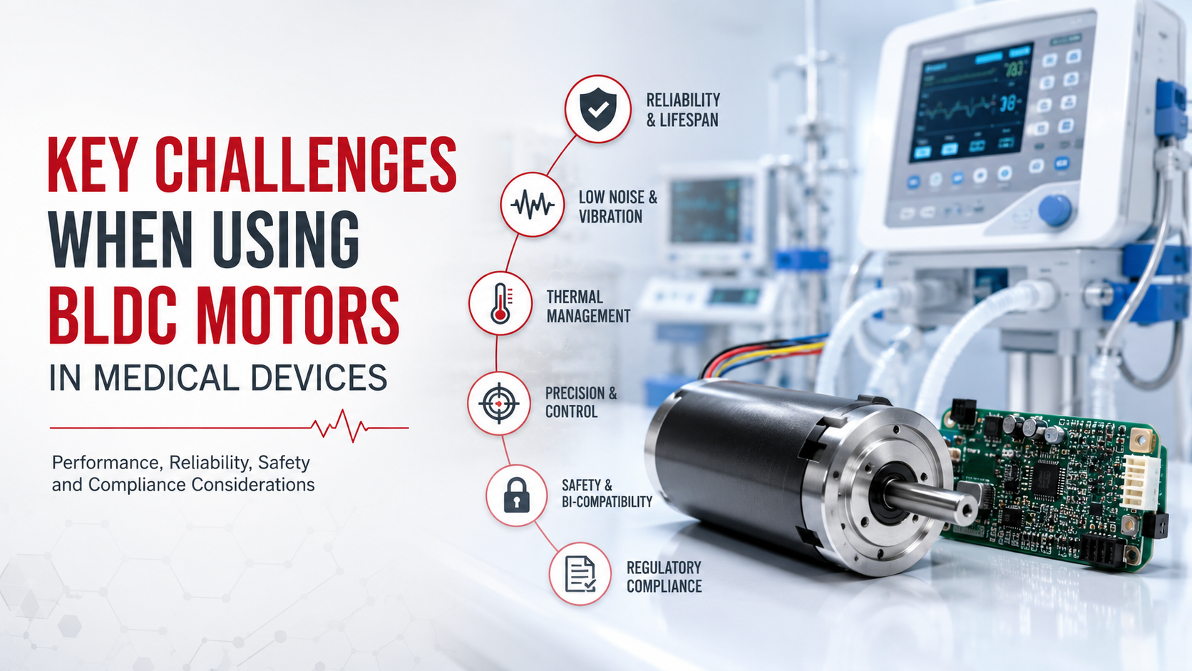
The main challenges when using a BLDC motor in medical devices are electromagnetic compatibility (EMC), acoustic noise and vibration, thermal management, precise speed and torque control, long-term reliability, sterilization compatibility, and material safety.
Unlike general industrial equipment, a medical device must maintain its required function under defined electrical, mechanical, thermal, and environmental conditions, so selecting a BLDC motor based only on rated voltage, speed, and torque is usually insufficient. The motor, controller, power supply, mechanical transmission, bearings, sensors, and surrounding medical system must be evaluated as an integrated system.
IEC 60601-1:2005+A1:2012+A2:2020 establishes general requirements for the basic safety and essential performance of medical electrical equipment, while IEC 60601-1-2 specifically addresses electromagnetic disturbances affecting medical electrical equipment and systems. The FDA recognizes IEC 60601-1 Edition 3.2 and relevant EMC standards for medical-device applications.
EMC and Electrical Noise
One of the most important challenges is controlling the electromagnetic noise generated by the BLDC motor and its electronic controller.
A BLDC motor normally requires electronic commutation, and the rapid switching of MOSFETs or other semiconductor devices produces voltage and current transients that can create conducted and radiated electromagnetic interference. In a medical device containing sensitive sensors, measurement circuits, communication interfaces, or monitoring electronics, this interference can become a system-level reliability problem.
The FDA-recognized IEC 60601-1-2 standard addresses both electromagnetic disturbances affecting medical electrical equipment and electromagnetic emissions generated by the equipment. The FDA’s recognized-standard database lists IEC 60601-1-2:2014, including Amendment 1:2021, for basic safety and essential performance under electromagnetic disturbances.
Engineering Solutions
A medical BLDC motor system may require:
- Shielded motor cables
- Proper grounding and cable routing
- Low-EMI motor driver design
- Controlled MOSFET switching slew rates
- Input and output filtering
- Optimized PCB layout
- Appropriate Hall-sensor wiring
- Ferrite components or common-mode filtering where required
- EMC testing at the complete-device level
Common mistake: Testing the motor alone for EMC and assuming that the final medical device will have the same result. In practice, the motor, controller, cable harness, power supply, chassis, and mechanical structure can interact and produce substantially different EMC behavior.
Acoustic Noise and Mechanical Vibration
Medical equipment often operates close to patients and healthcare professionals, which makes acoustic noise and vibration more important than they are in many industrial applications.
A BLDC motor can generate vibration through electromagnetic torque ripple, cogging torque, rotor imbalance, bearing variation, shaft misalignment, and mechanical resonance. PWM frequency and commutation strategy can also influence the acoustic spectrum.
For precision equipment such as pumps, laboratory instruments, imaging accessories, and automated medical mechanisms, even relatively small periodic disturbances can affect measurement stability or user comfort.
Typical Engineering Targets
Depending on the application, engineers may establish requirements such as:
| Parameter | Example Engineering Target |
| Motor speed | 1,000–10,000 rpm |
| Speed regulation | ±1–5% |
| Shaft runout | Typically controlled to tens of μm |
| Vibration | Application-specific, often specified by RMS acceleration |
| Acoustic noise | Often targeted below 40–50 dBA for quiet equipment |
| Speed ripple | Application-dependent, minimized for precision pumping |
These values are typical engineering targets rather than universal medical-device limits; the actual acceptance criteria must be derived from the device’s intended function and applicable standards.
Better Approach
Instead of selecting a motor only from its rated torque, evaluate:
motor + controller + load + mounting structure + bearing system + operating speed
as one dynamic system.
A rotor balancing test, vibration measurement, bearing selection review, and resonance analysis should be included when low-noise operation is important.
Thermal Management in Compact Medical Equipment
Thermal management becomes difficult when a BLDC motor must deliver continuous torque inside a compact enclosure with limited airflow.
Motor losses can be simplified as:
P_loss ≈ P_copper + P_core + P_mechanical + P_controller
Copper loss is approximately:
P_copper = I²R
Therefore, even a relatively small increase in motor current can produce a significant increase in winding heat.
For example, if winding current increases from 1 A to 1.5 A, the theoretical copper loss increases by:
(1.5 / 1)² = 2.25
or approximately 125% higher.
This is particularly important in medical devices because reducing motor size without considering heat transfer can create a thermal bottleneck.
Engineering Solutions
Engineers should evaluate:
- Continuous and peak load conditions
- Ambient temperature
- Motor mounting surface
- Enclosure thermal resistance
- Winding temperature rise
- Controller losses
- Duty cycle
- Maximum allowable surface temperature
A motor rated for 100 W mechanically does not necessarily mean it can continuously deliver 100 W inside a small sealed medical enclosure.
Precise Speed and Torque Control
Many medical systems require stable fluid flow, accurate positioning, or repeatable mechanical movement, making speed regulation more important than simply achieving a nominal RPM.
For example, a BLDC motor used in a medical pump may need stable operation across changing pressure and flow conditions. A research prototype for left atrial circulatory assistance reported a custom three-phase brushless, sensorless DC motor driving a compact pump capable of operating up to 10 L/min and 180 mmHg pressure rise, demonstrating how BLDC motor design can become closely coupled with pump performance. The study was published in 2022 by researchers reporting through the NIH/PubMed Central system.
For precision applications, engineers should consider:
- Hall sensors versus sensorless control
- Encoder feedback
- Closed-loop speed control
- Torque ripple
- Minimum controllable speed
- Startup behavior
- Load-transient response
- Controller resolution
Common mistake: Selecting a motor with sufficient maximum RPM but insufficient low-speed controllability.
Reliability and Bearing Life
Medical equipment may operate continuously or repeatedly for thousands of hours, so reliability must be evaluated beyond the motor’s initial performance.
Important failure mechanisms include:
- Bearing wear
- Lubricant degradation
- Magnet degradation
- Winding insulation aging
- Hall-sensor failure
- Connector fatigue
- Rotor imbalance
- Thermal cycling
- Excessive axial or radial load
A useful engineering approach is to define the actual operating profile before specifying the motor, including RPM, torque, duty cycle, ambient temperature, acceleration/deceleration frequency, radial load, axial load, and expected service life.
For example, specifying “5,000 rpm continuous” is incomplete unless the engineer also defines the load torque, operating temperature, bearing arrangement, and required lifetime.
Sterilization, Materials, and Biocompatibility
Material selection becomes especially important when the motor or its components can have direct or indirect contact with the patient, fluids, or a sterilization environment.
The FDA’s September 2023 guidance on ISO 10993-1 explains that biocompatibility evaluation considers the medical device in its final finished form, including factors such as materials, processing, manufacturing methods, sterilization, and potential residual substances.
The FDA also distinguishes contact duration as:
Limited: ≤24 hours
Prolonged: >24 hours to 30 days
Long term/permanent: >30 days
The applicable biological endpoints depend on the device category and contact conditions.
Therefore, engineers should not assume that a commercially available motor is automatically suitable for sterilizable or patient-contact applications.
The motor design may need appropriate:
- Stainless-steel components
- Sealing systems
- Low-outgassing materials
- Sterilization-compatible insulation
- Lubricants
- Surface treatments
- Encapsulation materials
BLDC Motor Challenges: Comparison Table
| Challenge | Typical Cause | Engineering Solution |
| EMC interference | PWM switching and current transients | Filtering, shielding, grounding |
| Acoustic noise | Torque ripple, bearings, imbalance | Rotor balancing, optimized commutation |
| Vibration | Mechanical resonance and imbalance | Dynamic balancing and rigid mounting |
| Overheating | I簡R losses and poor heat dissipation | Thermal design and derating |
| Speed instability | Load variation or inadequate feedback | Closed-loop control |
| Short lifetime | Bearing or insulation stress | Life testing and thermal analysis |
| Sterilization problems | Material degradation | Sterilization-compatible materials |
| Material risk | Leachables or unsuitable materials | ISO 10993-based evaluation |
Step-by-Step BLDC Motor Selection for Medical Devices
Step 1: Define the Load
Determine continuous torque, peak torque, speed range, acceleration, radial load, and axial load.
Step 2: Define the Operating Environment
Specify ambient temperature, humidity, enclosure conditions, sterilization exposure, and expected duty cycle.
Step 3: Select the Feedback Method
Use Hall sensors for cost-effective commutation, while encoders may be preferred where accurate position or speed control is essential.
Step 4: Evaluate Thermal Performance
Calculate continuous losses and verify winding and housing temperatures under worst-case operating conditions.
Step 5: Evaluate EMC
Test the complete motor-controller-cable assembly rather than relying only on component-level test results.
Step 6: Validate Reliability
Conduct endurance, thermal cycling, vibration, bearing-life, startup, overload, and abnormal-condition testing appropriate to the device.
Step 7: Validate the Complete System
The final validation should demonstrate that the motor does not compromise the medical device’s required basic safety and essential performance, which are central concepts in IEC 60601-1.
Troubleshooting Table
| Problem | Possible Cause | Recommended Check |
| Motor is too noisy | PWM frequency, bearings, resonance | Measure acoustic spectrum and vibration |
| Medical sensor becomes unstable | EMI from controller | Conduct EMC and cable-routing tests |
| Motor overheats | Excessive current or insufficient cooling | Measure winding temperature and current |
| Speed fluctuates | Poor feedback or load variation | Check Hall/encoder signals |
| Motor fails during startup | Insufficient starting torque | Test startup under worst-case load |
| Bearing life is short | Excessive radial/axial load | Review mechanical load calculations |
| Sterilization damages motor | Material incompatibility | Test insulation, seals, adhesives and lubricants |
| Pump flow is unstable | Torque/speed ripple | Analyze motor-control-pump interaction |
Common Engineering Mistakes
The most common mistake is treating the BLDC motor as an isolated component rather than as part of a medical mechatronic system.
Other frequent mistakes include selecting a motor based only on peak torque, ignoring controller-generated EMI, testing thermal performance at room temperature only, overlooking bearing loads, using non-validated lubricants or adhesives, and postponing EMC and reliability testing until the final prototype.
For regulated medical equipment, this approach can create expensive redesigns because changing the motor late in development may affect mechanical dimensions, firmware, EMC performance, thermal behavior, risk analysis, and verification testing simultaneously.
FAQ: BLDC Motors in Medical Devices
Is a BLDC motor suitable for medical devices?
Yes. A BLDC motor can be suitable for medical devices when its electrical, mechanical, thermal, EMC, reliability, material, and environmental characteristics meet the requirements of the complete device.
Why are BLDC motors used in medical equipment?
BLDC motors provide electronically controlled commutation, good efficiency, compact packaging, and precise speed control, making them useful for pumps, laboratory automation, medical mechanisms, ventilation equipment, and other applications.
Are BLDC motors quiet enough for medical equipment?
They can be, but low noise is primarily a system-design problem involving electromagnetic torque ripple, bearings, rotor balance, PWM strategy, mounting structure, and mechanical resonance.
Do medical BLDC motors need Hall sensors?
Not necessarily. Hall-sensored, sensorless, and encoder-based configurations can all be used, depending on startup requirements, speed range, control accuracy, and system architecture.
What standards are important for BLDC motors used in medical devices?
IEC 60601-1 addresses basic safety and essential performance of medical electrical equipment, while IEC 60601-1-2 addresses electromagnetic disturbances and EMC-related requirements. The FDA recognizes relevant editions of these standards for medical-device applications.
Does the motor itself need to be FDA approved?
Not necessarily. Regulatory requirements generally apply to the finished medical device and its applicable components, testing, risk management, and intended use; whether a particular motor requires specific documentation depends on how it is integrated into the device and the applicable regulatory pathway.
Related blog: How Electric Motors Drive Medical Devices?