
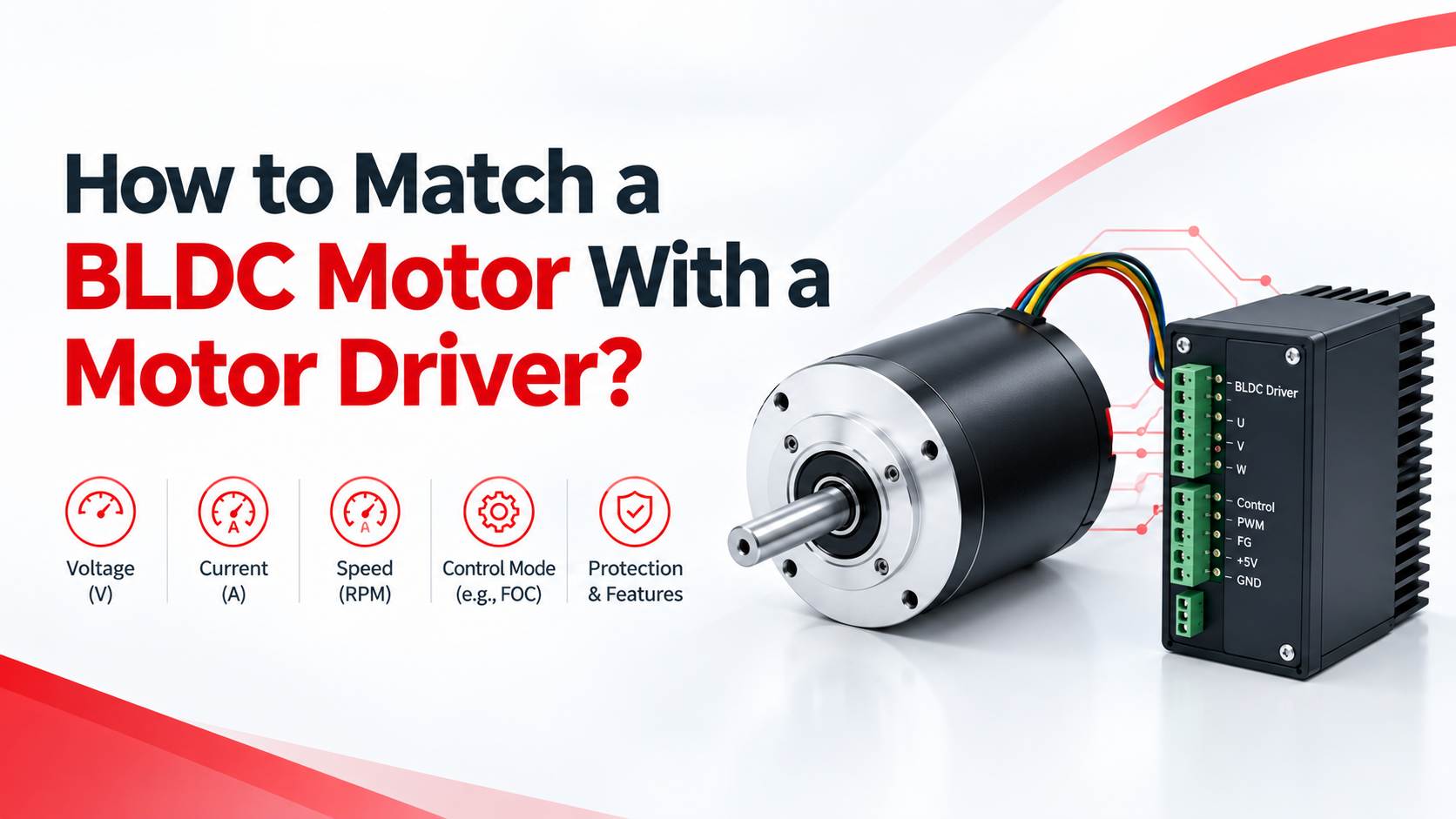
Selecting a BLDC motor and a motor driver as separate components is not simply a matter of matching the rated voltage and current; the driver must also be compatible with the motor’s phase configuration, feedback method, electrical characteristics, speed range, torque requirements, acceleration profile, and thermal operating conditions.
For OEM equipment, a correctly matched BLDC motor and driver should be treated as one motion-control system. UNITED MOTION INC. provides BLDC motors in 28–110 mm frame sizes, with multiple voltage options, Hall sensors, encoder integration, gearbox integration, and driver integration for industrial automation, robotics, electric mobility, solar tracking, pumps, and lawn equipment.
Quick Answer: How Do You Match a BLDC Motor With a Driver?
To match a BLDC motor with a motor driver, verify these eight parameters:
- Motor voltage and the driver’s DC bus voltage range
- Continuous and peak current requirements
- Motor power, torque, and operating speed
- Three-phase configuration and winding characteristics
- Hall sensor, encoder, or sensorless feedback compatibilit
- Control method, such as six-step or sinusoidal/FOC control
- PWM frequency and command interface
- Protection, cooling, and environmental requirements
The driver should satisfy the motor’s electrical requirements under the actual load, rather than simply having the same nominal voltage printed on the motor label.
Match the Motor Voltage With the Driver
The first check is the motor’s rated DC voltage.
For example, if a BLDC motor is specified for 24 VDC, the selected driver must have a DC input range that safely includes the application’s actual supply voltage and voltage transients. A driver designed for a substantially different bus voltage may cause insufficient output capability, excessive current, or component stress.
However, engineers should not interpret voltage matching as simply choosing a driver marked “24 V.” The battery or power supply tolerance, regenerative voltage, startup conditions, and wiring losses also need to be considered.
UNITED MOTION INC. lists multiple BLDC motor voltage options and recommends matching motor voltage with the battery or DC power supply.
Practical check
| Motor requirement | Driver requirement |
| 24 VDC nominal | DC input range must include 24 V |
| 48 VDC nominal | DC bus must safely support 48 V |
| Variable battery voltage | Driver must tolerate full battery operating range |
| Regenerative load | Check driver’s DC bus overvoltage protection |
Match Continuous and Peak Current
Current capability is often more important than nominal motor power when selecting a driver.
A motor may require relatively low current during steady-state operation but substantially higher current during startup, acceleration, reversing, or transient load conditions. Therefore, compare the motor’s continuous current and peak/starting current with the driver’s continuous and peak output ratings.
For example, if a motor requires 8 A continuously and 16 A during acceleration, selecting a driver rated at only 8 A may result in current limiting, overheating, or failure to accelerate the load.
Engineering rule
Do not size the driver only from:
Motor rated power ÷ supply voltage
Instead, examine:
Continuous current + peak current + duration of peak current + thermal conditions
The driver’s peak-current specification should also be checked for its actual duration and cooling conditions.
Match Torque and Speed
A compatible driver must allow the motor to reach the required operating point.
Motor mechanical output can be approximated by:
P = T × ω
where:
- P = mechanical power in watts
- T = torque in N·m
- ω = angular velocity in rad/s
For example, a motor delivering 1 N·m at 3,000 rpm produces approximately 314 W of mechanical power.
This calculation is useful for determining whether the motor-driver combination is fundamentally appropriate, but it does not replace the manufacturer’s torque-speed curve.
UNITED MOTION INC. recommends determining continuous torque, peak torque, required operating speed, and maximum RPM during BLDC motor selection.
Check Hall Sensors and Feedback Compatibility
A major source of BLDC startup problems is an incorrect feedback configuration.
A sensored BLDC motor commonly uses three Hall signals to identify rotor position. In a six-step control system, the controller uses the Hall pattern to determine which motor phases should be energized.
Microchip Technology’s May 2026 developer documentation explains that three Hall sensors provide a digital rotor-position pattern corresponding to six valid electrical sectors, with the controller using this information to control the three-phase inverter.
Therefore, check:
- Hall sensor voltage
- Hall signal logic
- Hall sequence
- Connector pinout
- Electrical phase sequence
- Direction of rotation
A motor and driver can have identical voltage and current ratings and still fail to start correctly if the Hall and phase relationships are incompatible.
Decide Between Sensored and Sensorless Control
A BLDC motor does not necessarily require Hall sensors.
Sensored control uses Hall sensors or an encoder to provide rotor-position information, making it particularly useful where reliable startup and low-speed operation are important.
Sensorless control estimates rotor position from electrical characteristics such as back-EMF. Microchip’s 2016 application documentation notes that sensorless commutation can eliminate position sensors, wiring, and connectors, but requires sufficient motor speed for reliable position estimation.
| Control method | Main advantage | Typical consideration |
| Hall sensored | Reliable position feedback | Requires Hall wiring |
| Encoder feedback | Higher-resolution position information | Higher system complexity |
| Sensorless | Fewer sensors and wires | Low-speed startup can be challenging |
| Six-step | Simple implementation | More torque ripple/acoustic noise |
| Sinusoidal/FOC | Smooth control and precise regulation | More complex electronics/software |
Microchip identifies Hall-based six-step commutation as a common and reliable BLDC control method, while also documenting sensorless six-step control based on back-EMF zero-crossing detection.
Match the Driver’s Control Interface
The motor may be mechanically compatible with the application while the driver is electrically incompatible with the machine controller.
Before purchasing, verify whether the driver accepts:
- PWM speed command
- Analog voltage
- Pulse/direction
- CAN or other communication interfaces
- Enable/disable signals
- Direction commands
- Encoder feedback
Also verify the PWM frequency and control range.
Check Thermal and Protection Requirements
A motor driver should be evaluated under the application’s worst-case operating condition, not only at nominal load.
Important protection functions include:
- Overcurrent protection
- Short-circuit protection
- Overtemperature protection
- Undervoltage protection
- DC-bus overvoltage protection
- Stall protection
Thermal performance is especially important because semiconductor losses increase with current, while enclosure temperature and insufficient airflow can reduce the driver’s usable continuous-current capability.
The U.S. Department of Energy emphasizes evaluating motor systems as complete systems rather than focusing only on individual components, while its motor-system resources include guidance on motor-drive interactions, operation, and efficiency.
Common BLDC Motor and Driver Matching Problems
| Problem | Likely cause | Engineering check |
| Motor does not start | Incorrect Hall sequence | Verify Hall pattern and phase wiring |
| Motor vibrates | Incorrect commutation | Check phase/Hall relationship |
| Driver trips during acceleration | Peak current too low | Compare startup current with driver rating |
| Motor overheats | Excessive load/current | Check torque, current and cooling |
| Motor reaches low speed only | Incorrect voltage or current limit | Check DC bus and current settings |
| Sensorless motor fails at startup | Insufficient back-EMF | Consider Hall feedback |
| Excessive acoustic noise | Commutation/PWM characteristics | Evaluate six-step vs sinusoidal/FOC |
| Speed is unstable | Feedback or control mismatch | Check Hall/encoder signals and control loop |
Common Mistakes When Selecting a BLDC Driver
Mistake 1: Matching voltage only
A 24 V driver is not automatically compatible with every 24 V BLDC motor.
Mistake 2: Using rated current as the peak requirement
Startup and acceleration can require substantially more current than steady-state operation.
Mistake 3: Ignoring feedback
Hall sensor wiring and commutation sequence must be compatible with the driver.
Mistake 4: Ignoring the load profile
A motor that works at no load may fail when connected to a gearbox, pump, conveyor, actuator, or other mechanical load.
Mistake 5: Selecting components independently
For OEM applications, integrating the BLDC motor, gearbox, encoder/Hall sensor, and driver can reduce compatibility problems and simplify system validation. UNITED MOTION INC. supports motor dimensions, winding design, voltage/speed, shaft design, Hall sensors, encoder integration, gearbox integration, and driver integration for customized BLDC motor solutions.
A Practical BLDC Motor-Driver Selection Process
For an engineering project, use this sequence:
- Step 1: Define load torque and speed.
- Step 2: Calculate continuous and peak mechanical power.
- Step 3: Select the motor voltage and winding configuration.
- Step 4: Determine continuous and peak motor current.
- Step 5: Select Hall, encoder, or sensorless feedback.
- Step 6: Select a compatible three-phase BLDC driver.
- Step 7: Verify voltage, current, control interface, and protection ratings.
- Step 8: Test startup, acceleration, steady-state operation, reversing, thermal rise, and stall conditions.
This system-level approach is important because motor-driven systems represent a significant portion of industrial electricity consumption; the IEA reported in 2011 that electric motor-driven systems accounted for more than 40% of global electricity consumption, highlighting the importance of optimizing the complete motor-drive system rather than treating the motor as an isolated component.
FAQ: BLDC Motor and Driver Matching
Can any BLDC driver work with any BLDC motor?
No. The driver’s voltage, current, commutation method, feedback interface, control algorithm, and phase configuration must be compatible with the motor.
Does a BLDC motor need a motor driver?
Yes. A conventional BLDC motor requires electronic commutation, normally through a three-phase inverter and motor controller.
Can I run a BLDC motor without Hall sensors?
Yes. Sensorless control can estimate rotor position from back-EMF, although startup and low-speed performance require careful evaluation.
How much current should a BLDC driver provide?
The driver should support the motor’s required continuous current and the required peak current during startup, acceleration, reversing, and transient loading, with thermal conditions included in the calculation.
Is a higher-current driver always better?
Not necessarily. Excess capacity can be useful, but the driver still needs compatible voltage, feedback, control logic, commutation characteristics, and protection settings.
Can a gearbox be combined with a BLDC motor and driver?
Yes. A geared BLDC motor can be used when the application requires higher output torque and lower speed, provided the motor, gearbox, and driver are sized according to the complete load profile.