
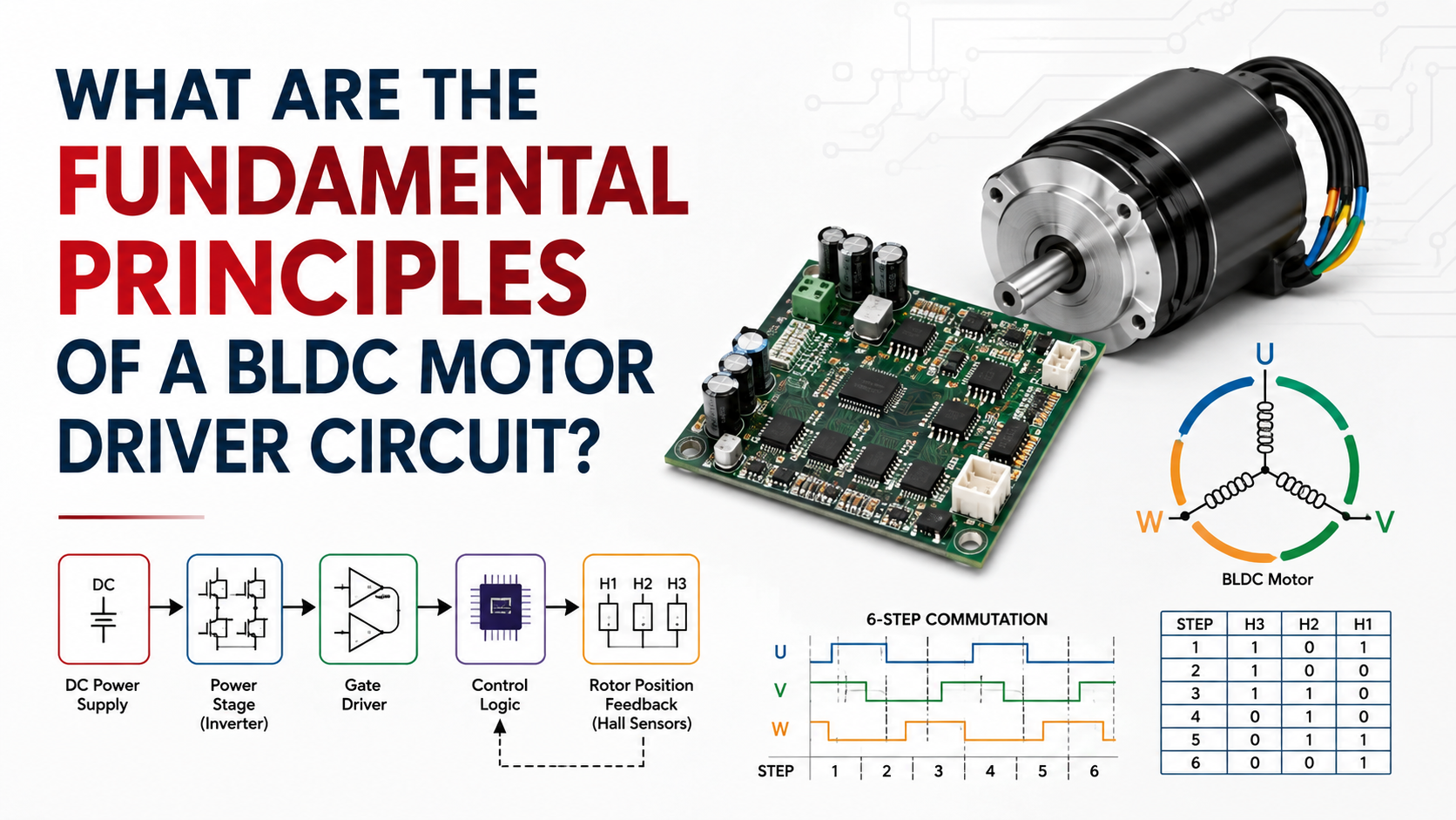
A BLDC motor driver circuit converts DC electrical power into controlled three-phase current for a brushless DC motor by coordinating rotor-position detection, electronic commutation, PWM voltage control, current regulation, and power-switch protection. In a conventional six-step BLDC system, three Hall sensors identify the rotor’s electrical position, a microcontroller or motor-control IC interprets the Hall pattern, and a three-phase inverter consisting of six MOSFETs switches the motor phases in the correct sequence. Microchip’s 2026 technical documentation describes Hall-based six-step commutation as a common BLDC control method in which Hall signals determine the inverter switching pattern.
For an engineer, the most important principle is that the driver does not simply apply DC voltage to the motor; it continuously determines which phase pair should conduct, when switching should occur, and how much effective voltage or current should be applied according to rotor position, speed, load, and protection limits.
What Does a BLDC Motor Driver Circuit Actually Do?
A BLDC motor is electronically commutated, meaning that mechanical brushes and a commutator are replaced by semiconductor switches and electronic control logic. The driver therefore becomes the electrical equivalent of the mechanical commutator found in a brushed DC motor.
A typical BLDC Motor Driver Circuit contains five functional sections:
- DC power supply and DC-link capacitor
- Three-phase MOSFET inverter
- Gate-driver circuit
- Microcontroller or motor-control IC
- Position, current, voltage, and temperature feedback
The controller determines the required switching state, while the MOSFET bridge supplies current to the motor windings. Microchip’s motor-control implementation specifically uses Hall position feedback, PWM generation, ADC current measurement, and timing functions as coordinated elements of the control system. (Microchip Technology, 2025–2026.)
The Three-Phase Inverter Is the Power Core
The fundamental power stage normally consists of six MOSFETs arranged as three half-bridges, with one half-bridge connected to each motor phase: U, V, and W.
For a typical low-voltage system, such as a 24 V or 48 V BLDC motor, the MOSFET voltage rating must provide sufficient margin above the nominal DC-bus voltage because switching transients, regenerative energy, wiring inductance, and load changes can produce voltage spikes.
The six switches can be represented as:
- High-side U / Low-side U
- High-side V / Low-side V
- High-side W / Low-side W
During conventional six-step commutation, two motor phases are normally energized while the third phase is left floating. Texas Instruments describes this as a fundamental characteristic of six-step BLDC control.
Why MOSFET selection matters
MOSFET selection should consider:
- Bus voltage
- Continuous and peak phase current
- RDS(on)
- Switching frequency
- Gate charge
- Thermal resistance
- Avalanche capability
- Package parasitics
For example, a 48 V motor system operating at 20 A does not mean the MOSFET simply needs a 20 A rating; the designer must consider peak current, transient conditions, thermal conditions, switching losses, and the actual RMS current waveform.
Electronic Commutation: The Fundamental Operating Principle
The rotor contains permanent magnets, while the stator contains energized windings. The driver must repeatedly change the energized winding combination so that the stator’s rotating magnetic field remains correctly aligned with the permanent-magnet rotor.
In a six-step system, one electrical cycle is divided into six commutation sectors.
A simplified sequence is:
| Step | Phase U | Phase V | Phase W |
| 1 | + | − | Floating |
| 2 | + | Floating | − |
| 3 | Floating | + | − |
| 4 | − | + | Floating |
| 5 | − | Floating | + |
| 6 | Floating | − | + |
The exact sequence depends on motor winding connection, Hall-sensor orientation, and desired rotation direction. A wrong phase/Hall relationship can cause vibration, excessive current, poor starting, or reverse rotation.
Texas Instruments’ BLDC commutation documentation shows the Hall-state-to-phase-switching relationship used to determine the six inverter states. (Texas Instruments, 2023.)
Hall Sensors Provide Rotor Position Information
A sensored BLDC motor commonly uses three Hall-effect sensors positioned approximately 120 electrical degrees apart.
The three digital signals create combinations that identify the rotor’s current commutation sector. The controller reads the Hall state and uses a lookup table to determine which MOSFETs should conduct.
For example:
Hall state → Commutation table → PWM outputs → MOSFET switching → Motor torque
Microchip’s May 11, 2026 technical documentation describes this exact architecture, including three Hall sensors, six MOSFET inverter switches, PWM outputs, and dead-time insertion.
One important engineering detail is that 120 electrical degrees is not necessarily 120 mechanical degrees. For a motor with multiple pole pairs, electrical angle and mechanical angle differ according to the motor’s pole-pair count. Texas Instruments explicitly notes this distinction in its Hall-sensor guidance.
PWM Controls Effective Motor Voltage and Speed
Commutation determines which phases conduct, while PWM determines how strongly they are driven.
If the DC bus is 48 V and the PWM duty cycle is approximately 50%, the simplified average applied voltage is approximately:
Vavg ≈ D × VDC
Therefore:
- 25% duty → approximately 12 V average
- 50% duty → approximately 24 V average
- 75% duty → approximately 36 V average
Actual motor winding voltage is more complicated because of back-EMF, winding resistance, inductance, switching topology, and current freewheeling paths.
PWM frequency is application-dependent, with values such as 10–25 kHz commonly encountered in practical low-voltage motor-control systems, although much higher frequencies may be selected when acoustic noise, current ripple, motor inductance, switching losses, and MOSFET characteristics justify the choice.
Microchip’s motor-control examples use dedicated PWM peripherals to generate the switching signals for the three-phase inverter.
Gate Drivers and Dead Time Prevent Shoot-Through
The MCU normally should not drive the MOSFET gates directly in a serious power stage. A gate-driver IC provides the required voltage, current capability, level shifting, and protection functions between the controller and MOSFETs.
One critical parameter is dead time.
When switching from a high-side MOSFET to a low-side MOSFET in the same half-bridge, the controller must ensure that the two devices are not simultaneously turned on. Otherwise, a direct short circuit from the DC bus to ground can occur, producing destructive shoot-through current.
Modern motor-control peripherals commonly provide programmable dead-time insertion. Microchip specifically identifies dead-time insertion as part of its three-phase inverter control implementation.
Current, Voltage, and Temperature Protection
A reliable BLDC Motor Driver Circuit requires more than commutation logic.
Current protection
Current sensing can be implemented through:
- Low-side shunt resistor
- Inline phase shunt
- DC-link current sensing
- Integrated current-sense amplifier
Current feedback is used for overload detection, torque control, current limiting, and fault protection.
Voltage protection
The driver should monitor:
- Undervoltage
- DC-bus overvoltage
- Regenerative voltage rise
- Switching transient
Thermal protection
MOSFET temperature, motor temperature, or driver IC temperature may be monitored to prevent thermal runaway.
Microchip’s BLDC reference implementation uses ADC resources for DC-link current measurement, demonstrating that current feedback is an integral part of practical motor-control architecture rather than an optional diagnostic function.
Sensored vs. Sensorless BLDC Driver Circuits
| Feature | Sensored BLDC | Sensorless BLDC |
| Rotor feedback | Hall sensors/encoder | Back-EMF or estimation |
| Starting from zero speed | Excellent | More difficult |
| Hardware cost | Higher | Lower |
| Wiring | More connections | Fewer connections |
| Low-speed control | Better | More challenging |
| Typical applications | AGV, actuator, automation | Fans, pumps, blowers |
| Control complexity | Lower | Higher |
Sensorless control typically estimates rotor position from back electromotive force (back-EMF) rather than directly measuring rotor position. Microchip’s AVR493 documentation notes that sensorless commutation eliminates position sensors, wiring, and connectors but requires sufficient motor speed for reliable back-EMF detection, making it particularly suitable for applications such as fans and pumps. (Microchip Technology, 2006; documentation updated subsequently.)
Common BLDC Driver Problems and Troubleshooting
| Problem | Likely Cause | Engineering Check |
| Motor does not start | Incorrect Hall sequence | Verify Hall-state table |
| Motor vibrates | Incorrect phase/Hall relationship | Check U/V/W and Hall wiring |
| High current at startup | Incorrect commutation | Measure phase current |
| MOSFETs overheat | Excessive switching or conduction loss | Check RDS(on), PWM frequency and thermal path |
| Motor runs backward | Incorrect phase sequence | Change commutation sequence |
| Noise is excessive | Poor commutation timing | Check Hall alignment and PWM strategy |
| Sensorless motor stalls | Insufficient back-EMF | Verify starting algorithm |
| MOSFET failure | Shoot-through/transients | Check dead time and DC-bus spikes |
A particularly common mistake is to assume that swapping any two motor wires will always solve a rotation problem; although phase swapping can reverse rotation in some configurations, the Hall sequence must remain synchronized with the new phase relationship, otherwise the motor may rotate inefficiently or draw excessive current.
Step-by-Step BLDC Driver Design Process
Step 1: Define the motor operating point
Start with:
- Rated voltage: for example, 24 V or 48 V
- Rated speed: for example, 3,000 rpm
- Rated power
- Continuous torque
- Peak torque
- Continuous and peak current
Step 2: Select the inverter
Select MOSFETs and a three-phase gate driver according to bus voltage, peak current, switching frequency, thermal environment, and expected transient voltage.
Step 3: Determine the feedback method
Choose Hall sensors when reliable starting and low-speed torque are important; choose sensorless control when reduced wiring and cost are more important and the application can tolerate the limitations of low-speed position estimation.
Step 4: Build the commutation table
Map every valid Hall state to the appropriate MOSFET switching state.
Step 5: Configure PWM
Select PWM frequency and duty-cycle limits according to motor inductance, acoustic requirements, MOSFET losses, and controller capability.
Step 6: Add protection
Include current limiting, overvoltage, undervoltage, overtemperature, short-circuit protection, and appropriate fault handling.
Step 7: Validate under load
Do not validate the driver only at no-load speed; measure phase current, DC-bus current, MOSFET temperature, motor temperature, vibration, acoustic noise, and commutation waveforms under representative mechanical loads.
FAQ
What is the main function of a BLDC Motor Driver Circuit?
Its main function is to convert DC power into controlled three-phase electrical excitation while synchronizing commutation with rotor position and regulating motor speed, torque, and current.
How many MOSFETs are normally used?
A conventional three-phase BLDC inverter uses six MOSFETs, arranged as three high-side/low-side half-bridges.
Does a BLDC motor need Hall sensors?
No. A BLDC motor can operate with Hall sensors, an encoder, or sensorless position estimation based on back-EMF, although sensorless starting and low-speed operation require additional control techniques.
What is six-step commutation?
Six-step commutation divides one electrical revolution into six switching sectors, with the inverter changing the energized phase combination according to rotor position.
What causes BLDC driver MOSFETs to overheat?
Common causes include excessive current, insufficient MOSFET voltage or current margin, high RDS(on), excessive switching frequency, inadequate dead time, poor PCB thermal design, insufficient heatsinking, and incorrect commutation.
Related blog: What is the Best Voltage for BLDC Motor?